VESSEL DESIGN AND CONSTRUCTION
(Ranger Hope © 2022, contains images courtesy of A.N.T.A. publications)
Principal Structures of a Vessel
Design Features and Terminology
The key maritime terms used in this text are described below:
Measured Length - Vessels subject to survey use tonnage or length to class vessels and determine specification requirements. Measured length is usually the distance from the fore part of the hull to the after part of the hull, taken at the upperside of the uppermost weathertight deck, or, in the case of open vessels, at the height of the gunwale. Figures 1 and 2 show two examples.

Fig. 1
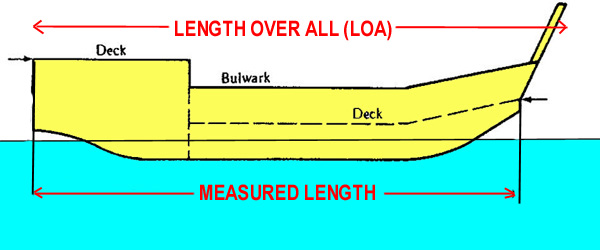
Fig. 2
Length Between Perpendiculars (LBP) (Fig. 3) - length from the forward perpendicular to the after perpendicular. The forward perpendicular is a vertical line drawn through the point where the load waterline cuts the stem. The after perpendicular is a vertical line drawn at the aft end of the rudder post.

Fig. 3
Length Overall (LOA) (Fig. 3) - the length from the extreme tip of the bow to the aftermost point of the stern.
Freeboard (Fig. 3) - the distance from deck to waterline.
Depth (Fig. 4) - the depth of a vessel is usually measured at the side and amidships, it is the distance from deck to keel.

Fig. 4
Beam or Breadth (Fig. 4) - is measured at the widest part of the vessel. It is the greatest width from one side of the vessel to the other.
A vessel in a normally loaded condition is said to be floating at its Load Waterline or Design Waterline (Fig. 3).
In that condition, the draft at which the vessel floats is called the Loaded Draught or sometimes the Service Draught. Draught is measured from the waterline to the deepest point of the vessel's hull, usually the underside of the keel. (Fig. 4).
Some vessels have a keel parallel to the design waterline. Some have a keel at an angle when compared with the design waterline called declivity of keel.
The bow is the region at the front of a vessel. (Fig. 5).
When facing forward, the part of the vessel on the left hand is the port side, the part on the right hand is the starboard side. (Fig. 5).
The stern is the region at the back of a vessel. (Fig. 5).

Fig. 5
A person moving towards the bow is said to be going forward or fwd. (Fig. 6).
A person moving towards the stern is said to going aft. (Fig. 6).
Amidships is the region in the middle of the length. Frequently this word defines the point at the middle of LBP.

Fig. 6
When moving along the length of a vessel a person is moving in a longitudinal direction.
When moving across a vessel a person is said to be moving in a transverse direction.
In some vessels the deck line curves forward and aft, this is called sheer. It aids water run off and contributes to reserve buoyancy. (Fig. 6).
Flat of Bottom - in some vessels, the area of the hull near to the keel is flat, this is called Flat of Bottom. (Fig. 7).
Rise of Floor (Deadrise) - if the bottom of a vessel rises from the centre line to the turn of bilge, there is said to be a Rise of Floor. (Fig. 7).
Bilge - the rounded part of the hull, where the side meets the bottom is called the bilge. A rounded bilge provides strength and reduces hull stresses. (Fig. 7).
Camber - if the deck of a vessel has an upward curve, it is said to have a camber. This helps water to run off the deck and reduces deck stresses. (Fig. 7).
Tumblehome - if the sides of a vessel, 'fall-in' towards the centre line as they rise to the deck-edge, the vessel is said to have tumblehome. This is less common these days.

Fig. 7
Flare - the outward flowing of the bow (called Flare) forces water outwards and away, promoting deck dryness and assisting
the bow to lift over waves. (See Fig. 8).

Fig. 8
Bow Rake is similar to flare in that it promotes deck dryness by forcing water forward when the bow strikes waves. See Fig. 9.

Fig. 9
Design Requirements
A vessel’s design is influenced by the following factors:
Nature of Service
Commercial Requirement
Area of Operation
Survey Requirements
Personnel Safety
Construction Materials
Seaworthiness, Stress and Stability
Nature of Service
A vessel is designed to perform a specific function such as carrying passengers, cargo or fish. It’s size, layout, accommodation, machinery and equipment are all related to the type of service it is meant to provide.
Commercial Requirements
Commercial requirements dictate that a vessel should be designed so as to keep the construction and operational costs at a level acceptable to its owner.
Area of Operation
Generally, a vessel that is required to spend longer periods at sea without replenishment will have a correspondingly larger capacity to carry fuel and stores. Weather conditions also influence design. Frequent rough conditions may require the decks to be located sufficiently high above the water to keep them reasonably dry. The size of the vessel may have to be increased to cope with adverse conditions.
Survey Requirements
A small vessel must be
designed, constructed and operated in accordance with the regulations contained
in the regulations of each licensing authority. This includes specifications
for materials, components and scantling sizes defined in the plans. Much of
the Australian legislation is contained in the National Standards for Commercial
Vessels, published by the Australian Maritime Safety Authority.
A vessel is surveyed by the marine authorities during the building stage,
on completion of building, and then periodically throughout its life to ensure
that it complies with the regulations.
Personnel Safety
Persons on board must have safe working areas, safe access to and from the working areas and safe accommodation. In the event of accidents and breakdowns at sea, necessary safety measures must be available as per statutory requirements.
Construction Materials
Each type of building material has its own advantages and disadvantages. The choice of building material will influence the carrying capacity, propulsion power requirements and construction method of the vessel.
Seaworthiness,Stress and Stability
A vessel must be designed to ensure that it is capable of surviving the variety of weather and operating conditions likely to be encountered in its area of operations. This means that under normal operating conditions, the vessel should have enough stability to keep it upright and afloat. Careful attention must be paid to the hull shape, the distribution of weights and the protection of hull openings.
A vessel’s structure should be able to withstand the stresses caused by:
-water pressure,
-action of wind and waves and
-weights on board such as cargo, machinery and its operations
A vessel is subject to both static and dynamic forces from the elements and from its working in a seaway. The weight of a static vessel acts downwards and is counteracted by the upward force of buoyancy, causing it to float at its designed waterline - Fig. 10. Water pressure acts at 90 degrees to all surfaces all around the underwater sections of the hull. The vessels skin needs to be sufficiently rigid that it does not collapse under this pressure but continues to keeps the water out (maintains watertight integrity).

Fig. 10
In a seaway the vessel is buffetted by the dynamic elements of wind and wave, causing it to move through six differing motions either singly or in combination. These dynamic forces cause the vessel to roll from side to side, to yaw by twisting on its longitudinal axis, to heave by bodily rising and falling, to pitch by alternately rising the bow and dipping the stern, to surge by moving aft and astern and to sway by moving to port and then to starboard.

Fig. 11
Forces acting over an area of a surface are calculated as stress. The five stresses are defined as:
Compression - the squashing of a component (e.g. hammering).
Tension - the stretching of a component to or beyond its limit of elasticity (e.g. pulling).
Shear - the interface of forces acting in contrary directions (e.g. unequal loading of adjoining compartments).
Torsion - the interface of a rotary force and a static one (e.g. engine bed bolts).
Flex - bending backwards and forwards (e.g. the bow structures plunging in and out of a seaway called panting).

Fig. 12
In considering stresses on a vessel in a seaway (Fig 12) the vessel's longitudinal strustures can be considered as a steel bar that is deformed by wave action. One moment the mid-section is supported by wave crests causing it to bend down at the bow and stern (hogging). Next moment the bow and stern are supported by the wave crests and the midships bends down (sagging). This repeated action results in flex with alternating zones of tension abutted against compression along a shear zone.
If the cargo had been unevenly loaded, empty buoyant holds could be abutted with full heavy holds creating additional shear zones at the meeting bulkheads.
As the waves increase the vessel will pitch into the seaway causing hammering on its bow structures. If the vessels bow comes fully clear of the sea it will smashes down on the surface with great force called pounding. This repeated action may well result in the bow plates flexing in and out, called panting.
Rolling can cause its unique distorsion to the vessel's structure by bending the box shape of the mid-sections out of square. This deformation is called racking.
Two opposing
strategies confront the designer in construction choice. First is the rigidity
or flexibility of structural
components required by the design to ensure weathering the forces and enduring
operational conditions. For instance in a small timber catamaran it may be
preferable to lash the deck beams to the hulls so they "give" not
break in a seaway, while in a large steel catamaran it may be better to mount
solid (inflexible) bolts and braces.
The second is whether to use a moulded one piece construction system (monocoque) with no seams (PVC, GRP or Ferro-cement) or one that is constructed from multi fastened or welded components (timber, steel, aluminium).
Vessels are built from a number of materials, each of which has advantages and disadvantages. An understanding of the qualities and workability of construction materials is required to determine these choices. In practice, small craft build often combines materials including innovative composite solutions. Larger ships however are mostly built of welded steel, with lightweight aluminium being utilised for light deck structures.
The common materials used in hull construction are:
Timber
Steel
Aluminium
Glass reinforced plastic (GRP)
Ferro-cement
Neoprene rubber (IRBs and RIBs)
Plastic (PVC)
Reed, hide and dugouts (Traditional small craft)
The common materials used in fastenings are:
Copper
(ductile metal resisting corrosion)
Bronzes (castable metal alloy of copper, tin and manganese)
Brass (metal alloy of zinc and copper, not suitable for immersed use)
Stainless steel grade 316 (corrosion resistant, non magnetic and brittle)
Galvanised (electrocoated zinc only suitable for occaisional immersion)
Timber
Advantages:
1. Light
2. Easy to work
3. Corrosion resistant
4. Not easily damaged
Disadvantages:
1. Expensive
2. Rots and harbours vermin
3. Burns
Steel
Advantages:
1. Cheap
2. Comparatively easy to build
3. Not easily damaged
4. Good fire resistance
Disadvantages:
1. Corrodes
readily
2. Heavy
3. Not easy to work
4. Very magnetic. Affects the compass.
Aluminium
Advantages:
1. Light
2. Does not rust - almost maintenance free
3. Easy to work
Disadvantages:
1. Expensive
2. Comparatively easily damaged
3. Low melting point - poor fire resistance
4. Corrodes rapidly in contact with other metals such as steel, copper, bronze
etc.
GRP (also called fibreglass)
Advantages:
1. Corrosion
free
2. Light
3. Comparatively easily repaired
4. Cheap - especially if part of a mass produced monocoque designs
Disadvantages:
1. Comparatively
easily damaged
2. Poor fire resistance
3. Skilled construction required
4. Suffers osmosis
Ferro-Cement
Advantages:
1. Cheap
2. Monocoque one piece hull, no seams
3. Not easily damaged
4. Fire resistant
5. Easily repaired
Disadvantages:
1. Chips
easily
2. Labour intensive construction required
3. Heavy
PVC
Advantages:
1. Cheap
especially if part of a mass produced monocoque designs
2. Monocoque one piece hull, no seams
3. Not easily damaged
Disadvantages:
1. Weathers
with UV exposure
2. Heavy
Principal Structures of a Vessel
A history of experiment by trial and error has resulted in vessels and their component parts being constructed to meet the forces and stress encountered at sea. Apart from rafts that float above the water, every vessel has a skin of material that keeps it watertight.The main body of a vessel being its shell (skin) and hull (supporting framework). This must be strengthened for the hogging, sagging, pounding, panting and racking stresses anticipated in the sea area of operations. As well as the hull, certain other areas experience extreme loads that require additional strengthening, typically achieved by the strategy of doubling (extra duty construction).

Fig. 13
Timber vessels longitudinal structures
Regardless of the material used in construction and the host of differing local names of component parts, the fuction of hull structures are similar. Even in monocoque construction, the shell is supported by internal stiffeners. In all but the smallest of craft it is common for the main stiffener to run longitudinally as a backbone to the vessel, called a keel and keelson. This is scarf jointed to a stem timber at the bow and to a sandwich of timbers at the stern called the deadwood. Together these form a landing for the planking shell which is rebated to the keel along the rabet line. This keel structure provides the necessary resistance to hogging and sagging. Figure 14 shows the keel of a typical timber vessel terminating in the stem timbers forward (bow) and stern post with transom (aft).

Fig. 14 Typical timber longitudinal section
This forward (bow) structure must be resistant against pounding and the number of frames and floors may be doubled for this purpose. Each side of the stem post may even be solid with closely packed frames called the knight's head. The natural hinge of keel to stem post is backed by a naturallly curved grown chock cut from a tree bough.

Fig. 15 Typical stem assembly (bow)
Likewise this aft area has closely packed floors around the stress point of the stern post and propeller shaft.

Fig. 16 Typical deadwood aft
Timber vessels transverse structures
The simplest of hull forms is the flat bottom or sharpie that is essentially a raft with side planks, While this type can take the ground, planes and is cheap to build its seakeeping abilities are limited. At the other end of the scale the round bottom type allows excellent sea keeping and strength to drive through a head sea. The chine and multichine type provides a compromise between the two.

Fig. 17 Timber hull forms
While the stem, keel and deadwood provide longitudinal strength it is the planking (timber) or shell plating (steel) that keeps the water out of the hull.The main stiffeners of the hull plank or plate called frames usually run from side to side, this arrangement being called a transversely framed structure. The frames are tied together with longitudinal stringers, the one at the uppermost deck edge being called a sheer clamp. The transverse frames are sometimes called sawn frames. However, if they are formed from a continuous soild timber they are called ribs (or timbers if steam bent into place).

Fig. 18 Typical hard chine hull
Figure 18 above shows a hard chine (or Vee ) hull. It is called hard because the topside meets the bottom at an angle as opposed to a “soft chine” hull where the topside meets the bottom in a curve. Figure 19 shows the bottom construction of a round bilge type hull.

Fig. 19 Typical round bilge type hull
In timber construction the bow frames are often doubled up to incease the resistance to the stresses of pitching and panting.
Similarly, additional floors at the forward end of the keel/keelson provide stregthening against pounding along the bow's forefoot.
Steel and aluminium vessels
Small steel and aluminium vessels typically use a main logitudinal structure of a minimal flat keel plate backed by an internal longitudinal keelson or girder.The keel forms the backbone of a vessel’s hull.This helps in resisting longitudinal bending of the hull against hogging and sagging. Beams support the deck. Brackets connecting frames and beams help resist the distortion of racking to the hull when the vessel rolls. Stiffening by side keelsons (girders) may be utilised, being welded to floors along the bottom sections.

Fig. 20 Typical chine construction
In the case where longitudinal side keelsons are not continuous (they cross over the floors) they are termed intercostal keelsons.

Fig. 21 Typical round bilge type hull
In larger vessels the keel may be of box section with its underside effectively flush with the external shell plating. The box section allows a tunnel for services and even shaft log. When the main stiffeners of a steel hull predominently run fore and aft, the arrangement is called a longitudinally framed structure and when they run side to side the arrangement is called transverse framing.

Fig. 22 Framing of a large steel vessel
Much stiffening is incorporated in the front end sections against the stresses of panting, pounding and panting.

Fig. 23 Fore end sections of a steel vessel

Figure 24 Fore end construction
Reinforcement against panting may include integral welded sections that box together the bulkheads, chain locker compartment and hawse stiffening.

Figure 25 Panting frame in fore end construction
As in timber construction this aft area has closely packed floors around the stress point of the stern post and propeller shaft.

Fig. 26 Rudder stock stiffening
The engine bed is particularly prone to the stress of torsion betwen the rotary engine and the solid engine bolts, and is consequently reinforced with additional girders and floors.

Fig. 27 Engine bed stiffening
Larger ships will have double bottom tanks that provide ballast and fuel storage but also insure the vessel against a breach in the underside of the hull. Around the turn of the bilge double bottom tanks are stiffened with margin plates. The tank tops and margins must be regularly inspected for corrosion, as a fracture on the outer skin would quickly fill a double bottom tank that was no longer airtight.

Fig. 28 Double bottom tanks
Watertight integrity
Weathertight means
That the structure or fitting will prevent the passage of water through the structure or fitting in any ordinary sea conditions.
Watertight means
a) In relation to a fitting above deck, that it is so constructed as to resist effectively the passage of water under pressure, except for slight seepage.
b) In relation to the structure of the vessel, capable of preventing the passage of water in any direction if the head of pressure were up to the freeboard deck, which in your case would mean the main deck.
Hull
Watertight Integrity
The
steel plating in a metal vessel, the planking in a wooden one, or the FRP
laminate, have as their primary purpose, the task of keeping the interior
of the vessel free from water. In all types of vessel construction, a structural
framework is built first to provide the strength. This, when combined with
the external covering, forms the hull. In steel and aluminium ships, the hull
is made watertight by welding the steel plates together and to the framework.
Often the frame is built upside down and the shell plating is welded onto
the inverted frame. The hull is then righted and the internal welds are completed.
This procedure allows for a better weld and hence improved water tightness
since all welds are 'downwelds'.
Vessels constructed of timber are not normally totally watertight but rely on seepage of water to swell the planking and thus make them watertight. FRP and ferro cement hulls are continuous with no joints and are inherently watertight, as is their deck/hull connection.

Fig. 29 Small vessel watertight spaces
All vessels, except the very smallest of craft, are subdivided internally into watertight compartments by means of vertical partitions called watertight bulkheads. In vessels which have a measured length of 16 metres or over, a special watertight bulkhead called a Collision Bulkhead is fitted near the bow. The number and placement of other watertight bulkheads is dependent upon the measured length of the vessel. Vessels 12.5 metres and over in measured length must have a watertight bulkhead at each end of the machinery space except where the machinery space is located at one end of the vessel.
Look at the profile plan of KFV Albatross in Fig. 30 below. The dotted lines rising vertically from the keel represent the watertight bulkheads. The first collision bulkhead is located at frame no. 4. It rises from the keel to the underside of the foredeck.
The second watertight bulkhead is located at frame no. 6. It rises from the keel to the underside of the main or freeboard deck. The space between the two bulkheads is called a cofferdam. A cofferdam is a void space that separates two tanks. Normally a cofferdam is only required to separate oil and water tanks.
The space enclosed between the second and third water tight bulkheads is the refrigerated hold. The engine room space is located between frames 25 and 35. You will notice that there is a watertight bulkhead at each end of the engine room, making a total of four watertight bulkheads in all. The bulkhead at the after end of the engine compartment is known as the after peak bulkhead.

Fig. 30 KFV Albatross
Openings
in Watertight Bulkheads
Openings may be necessary in watertight bulkheads to allow the passage of
pipes or electrical cables, and special arrangements are made to ensure that
the watertight integrity of the bulkhead is maintained. All pipes passing
through a watertight bulkhead must be flanged to the bulkhead and do not pass
directly through it (see Fig. 31). The pipe on the left has a valve incorporated
in it for filling the tank on the other side of the bulkhead. There is a spindle
running up to the main deck from where this valve can be operated. The siting
of the valve outside of the tank it is servicing reduces corrosion and maintenance.

Fig 31 Pipes passing through watertight bulkhead
Doors may also be necessary, in watertight bulkheads, to allow the vessel to continue its normal operation whilst at sea. These doors can be of either a sliding or hinged type and must be capable of operation from both sides of the bulkhead. (See Fig 32).

Fig 32 Internal Watertight Door
A trip switch is fitted to watertight openings which will sound the alarm if the door were opened while at sea. Doors providing access from the main deck to lower compartments must have sills, which serve the same purpose as hatchway coamings. The sill heights are the same as for hatch coamings. Access doors can be hinged and should be marked "THIS DOOR IS TO BE KEPT CLOSED AT SEA”.
Hull and Deck Openings
Access hatchways must have a raised coaming to reduce the amount of water that could enter the ship should a wave wash over the deck while the hatch was opened. The height of the coaming varies according to the ship’s length. A trip switch is fitted to watertight side door openings which will sound the alarm if the door were opened while at sea.

Fig 33 shows the hatchways on the fore deck of a vessel that provide access
to compartments below the main deck.

Fig. 34 Raised coaming and seals
When a hatchway is cut into the deck of a vessel, the corners are rounded to reduce stresses.

Fig. 35 shows a cut away section of a hatchway coaming.
Ventilators and Ventilators must be a minimum height above the deck and must have some means of making them watertight. This may be metal flaps, or in smaller vessels, wooden plugs and canvas covers. Airpipes, where exposed, should be of substantial construction and if the diameter of the bore exceeds 30mm bore then the pipe should be provided with means of closing watertight. Other watertight opennings include:
Side Scuttles (portholes)
Airpipes- All portholes below the main deck should have hinged metal covers (deadlights) that can be closed watertight.
Scuppers, Inlets and Discharges
All sea inlets are to be fitted with valves of steel or material of equivalent strength attached direct to the hull or approved skin fittings (in case of non metal hulls).
Drainage arrangements from weather decks
Weather decks are to be provided with freeing ports, open rails or scuppers capable of rapidly clearing the deck of all water under all weather conditions.
Maintenance
of Watertight Integrity
Watertight integrity can be breached through any activity or happening that
allows the ingress of water in unwanted areas or compartments of the vessel.
Typical
examples include:
Lack of maintenance to seals, (painting over seals), screw threads and other locking devices.
Damage caused by collision, grounding or heavy weather.
Leaving hatches, doors, vents etc open.
Blocked freeing ports or scuppers.
Cracks along welds in metal vessels or loss of caulking from planked seams in timber vessels.