DECK
MACHINERY & STEERING GEAR
(Ranger
Hope © 2008, contains edits of material courtesy of A.N.T.A. publications.)
Deck
Machinery
Steering Gear
Deck
Machinery
Common
items of deck machinery found on small vessels are the anchor windlass, winches and the
crane or derrick.
Anchor Windlass
The
anchor windlass is used for handling anchor chain. It is usually located in
an exposed position on the fore-part of the vessel,
hence most of its moving parts are enclosed. Routine maintenance is usually
carried out through the provision of grease nipples. Inspection of the equipment
frequently involves the opening of plates or panels in the cover.
Figure
2.1 shows a typical anchor windlass. The cable lifter (or gypsy) can be clutched
to the drive shaft by means of a simple dog clutch arrangement. The braking
arrangement is usually a band brake. Warping drums may be provided at the ends
of the drive shaft. These are used for heaving mooring ropes.
Maintenance of Anchor Windlass
Maintenance
should be strictly carried out as per the equipment manufacturer’s instructions.
However, general guidelines for maintenance are suggested as follows
:
Weekly
Charge
all grease points.
Operate
clutch through full travel.
Operate
windlass.
Six Monthly
Inspect
clutch plates and inspect for wear and corrosion
Examine
mechanical brake for wear.
Examine
base and mountings for corrosion.

Fig.
2.1 Anchor Windlass
Winches
Winches
are used to haul wires or ropes. They may be hand operated or driven by an electric
or hydraulic motor or a steam engine. Basically they consist of one or more
rotating drums on which a rope or wire may be wound and in some cases stored.
A winch with a drum rotating on a vertical axis is known as a capstan. Winches
are widely used with cranes, derricks and for mooring purposes.
1.2.1
Maintenance of Winches
A
winch requires the same care and maintenance as a windlass. In addition you
must check the condition of the associated wires and ropes prior to use to ensure
that they are free from breaks or frays. Wires should be regularly coated with
a lubricant to protect them from corrosion.
Cranes
Modern
cranes rely on a vessel’s power to electrically or hydraulically operate winch
drums and slewing gear. On many cranes three motions are possible - lifting,
slewing and luffing (raising or lowering the jib boom). Figure 2.2 shows a crane
where lifting and slewing motions are possible.
Cranes
should always be marked with their Safe Working Load.
|
|
 |
Figure
2.2 Slewing Davit Crane
Maintenance of Cranes
Suggested
maintenance schedule for cranes (similar to the one shown in fig 2.2):
Weekly
Turn
davit boom through normal arc by hand slewing gear.
Check
winch brake for freedom of action.
Inspect
brake lining for wear and grease deposits.
Conduct
running test with dummy load. Failure of this test will probably require the
replacement of brake linings.
Monthly
Lubricate
and grease all points on the crane.
Check
oil levels.
Check
brake linings for wear.
Clean
and examine all wire ropes and lubricate running gear.
Six Monthly
Examine
all parts for corrosion, distortion, cracks or any other defects.
Check
slewing gear for backlash.
Check
hand raising clutch, brake assembly and gear box clutch for damage, wear,
and oil contamination.
Survey Requirements
The
survey requirements for deck machinery are laid down in section 14 of the
USL Code. After the initial commissioning survey, deck machinery is surveyed
during annual and periodic surveys or as required by the appropriate authority.
The surveys include the inspection of windlass mounting and surrounding deck
to insure that these are adequate for their task and have not deteriorated
with use or due to corrosion. It is a requirement that the machinery should
operate as specified and within safe limits.
Any
gear (including cranes) used for handling cargo must comply with Commonwealth
regulations contained within Marine Orders Part 32 (Cargo and Cargo Handling
- Equipment Safety Measures)
Precautions in Deck Machinery Operations
Ensure
that operating and control handles are clearly marked to show ‘heave in’ and
‘pay out’ directions.
Never
exceed the safe working load of the equipment.
Never
operate the machinery if there is a fault in the clutch or brake.
Ensure
that gear wheels and other moving parts are always protectively covered.
Keep
the working area free from oil and grease.
Do
not operate the machinery if you cannot sight the load.
Ensure
that you know how to stop the running machinery in an emergency.
Always
use the machinery in the manner specified, and within the limits suggested
by the manufacturer.
Steering
Gear
Most
vessels are steered with the aid of a rudder, which is rotated to the required
angle by a steering mechanism. The type and size of steering mechanism depends
on the size and design of vessel.
Rudders
The
National Standards specify the sizes and materials used for the construction
of rudders. Two methods of mounting the rudder are shown in figure 2.3.
|
|
 |
Figure
2.3 Rudders
Drawing
(a) shows a mounting arrangement where the forces on, and the weight of the
rudder are carried by the rudder stock. This means that the stock and bearings
should be of adequate size and strength to withstand stresses under any weather
condition.
Drawing
(b) shows a pintle type rudder arrangement. The rudder is hung on pintles and
has a further pintle in the extension to the keel.
The
rudders are secured to the stock by flanged couplings and these
need to carefully checked whenever the vessel is out of the water.
Wire and Pulley
A
wire and pulley arrangement is shown in figure 2.4. which
consists of a wire wound around a drum fitted to the wheel. The wire passes
through a series of pulleys on the two sides which connect to the tiller or
quadrant of the rudder mechanism.To avoid excessive
strain and bending of the wire the pulley blocks should be as big as possible
and positioned to avoid an excessive angle or be easily fouled. Buffer springs
are provided on both port and starboard to prevent violent recoil of the steering
wheel. All components should be inspected and greased or oiled as appropriate.

Figure
2.4 Wire and Pulley
Chain and Box
A
wide variety of chain and box installations make use of automotive parts such
as shafts, universal joints and truck steering boxes. These systems require
periodic inspection and lubrication. The chain is liable to stretch and should
be checked regularly. For this reason the chain length is usually adjustable.

Figure
2.5 Chain and Box Gear
Push-Pull Cable
A
push-pull cable type steering arrangement is shown in figure 2.6. This arrangement
is similar to that used on outboard motors. The length of the cable should not
be too long or short as this can affect the tiller response. If the push-pull
cable or rod seizes, there must be provision for releasing the push-pull rod
from the tiller to operate the emergency steering.
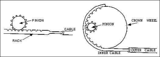
Figure
2.6 Push-Pull Cable Gear
Basic Hydraulic Systems
Hydraulic
systems are common in vessels of 20 metres or more in length. These systems
range from simple manual systems to electro-hydraulic oned.
Figure 2.7 shows a simple manual system with a single steering station.
The
system operates utilising the flow of hydraulic fluid under pressure to control
the movement and position of the rudder. The system consists of a two way hydraulic
pump, usually an internal gear pump, connected to the wheel. Two pipes lead
from the pump to the hydraulic cylinder and ram, which in turn is connected
to the tiller. The rotation of the wheel will force oil from the pump to one
side of the ram thus rotating the rudder.
A
major problem associated with any hydraulic system is air in the system therefore,
most systems are built to be self purging of air.
The
emergency steering will require the oil to be by-passed and a valve is placed
between the two sides of the system for this purpose. To prevent hydraulic locking,
this valve will need to be opened when the emergency system is to be operational.
In addition, there should be a relief valve which spills the oil from one side
to the other in the event of shock loading to the system.
Specific
maintenance requirement for this system is to ensure that the oil level is adequate
and that there are no leaks.
Figure
2.7 Simple Hydraulic System
Simple Telemotor
In
most larger systems the signal from the steering wheel
is transmitted to the steering gear by means of a telemotor. This not only ensures
that the steering system is isolated to the steering flat,
it also means that the steering system can be used even if the wheel and connections
are damaged or become inoperative.
Figure
2.8 shows a steering system incorporating a telemotor. The latter consists
of a transmitter in the wheelhouse and a receiver in the steering flat. The
movement of the wheel activates an hydraulic piston in the transmitter. The fluid displaced
by this piston is used to displace a similar piston in the receiver. This movement
is used to control the main steering gear’s hydraulic pump, which in turn operates
the steering gear and rudder. The receiver is usually spring loaded so that
the steering wheel will easily return to the midships position.
Figure
2.8 Steering Gear and Telemotor
Electro-Hydraulic
The electro-hydraulic
system, shown in figure 2.9, has the advantage that the signal from the wheelhouse
to steering flat is transmitted by electrical wires. Further, the system uses
a uni-directional pump which is less complicated and cheaper than a bi-directional.
The pump supplies
oil at a constant rate to a directional control valve, which is usually positioned
in the steering flat.
The valve consists
of three positions, and depending on the position, will supply oil to either
side of the double acting ram. When in the neutral position, oil is locked
in the ram, thus maintaining the given rudder angle, whilst the pump flow is
circulated back to the tank. The valve is operated by solenoids controlled
from the wheelhouse via the control box.
As with the previous system there is a by-pass and relief valve
fitted between the left and right sides of the ram.
Emergency steering can be carried out by operating the emergency steering lever
located in the steering flat.

Figure 2.9 Electro-hydraulic
System
Requirements for Steering Gears
Steering Gears
are surveyed during a vessel’s annual and periodic surveys. The requirements
for steering gears are laid down in the
National Standards.
. These are summarised
below.
General Design
All vessels except
twin screw vessels and vessels where the normal means of steering is a hand
tiller shall be fitted with two independent means of steering.
The steering gear
shall be of adequate strength to steer the vessel at maximum speed both ahead
and astern.
Rudder movement
should be 35 degrees port and starboard.
In vessels 12.5m
and over the steering gear shall be capable of putting the rudder from 35 degrees
on one side to 30 degrees on the other in 30 seconds at maximum speed.
The steering gear
shall be so designed and constructed to prevent violent recoil of the steering
wheel.
In hydraulic systems,
changing over from primary to secondary systems should be able to be carried
out easily and quickly.
Power driven hydraulic
systems shall be fitted with a relief valve to prevent mechanical damage.
The rudder indicator
shall move in the same direction and give a true indication of the rudder angle.
If the emergency
steering is remote from the steering/navigation position an adequate form of
communication between these two positions shall be installed.
Where necessary
the steering gear will be fenced and have adequate guards to avoid injury to
personnel.
As stated above
if the tiller and hence the rudder is rotated by hand as in small vessels it
is not required to have a back up or emergency system. However, in most modern
vessels a mechanical means is employed to move the tiller, thus requiring an
emergency back up. This may take the form of a hand tiller,
which can be quickly and easily fitted to the top of the rudder stock.
This emergency tiller must be kept in a place close to the steering flat and
stock.
Survey Requirements
The
National Standards specify the
survey schedule is as follows:
Annual Survey: Operational test of main and emergency
means of steering.
2 Yearly Survey: Inspection of Rudders.
8 Yearly Survey: Steering gear.
Operation, Testing and Drills
The
National Standards specify detailed
procedures concerning the safety of navigation. These procedures are summarised
below :
If the vessel
is fitted with an automatic pilot the manual steering shall be tested after
prolonged use and before entering areas where navigation requires special caution.
Within 12 hours
before departure the vessel’s steering systems shall be checked and tested,
where applicable by the operation of the following:
1. the main steering gear
2. the auxiliary system
3. the remote steering gear control system
4. the wheelhouse steering position
5. the emergency power supply
6. the rudder angle indicators
7. the system power failure alarms.
Tests and checks
shall include :
1. the full and accurate movement of the rudder
2. visual inspection of all parts and linkages
3. the operation of the means of communication between the wheelhouse
and steering gear compartment
Simple operating
instructions and a block diagram should be permanently displayed in the wheelhouse
and steering gear compartment.
Emergency steering
drills shall take place at least once every three months.
Details of all
tests, checks and emergency steering drills shall be recorded in the log book
or the vessel record book.