BILGE PUMPING SYSTEMS
(Edited extracts courtesy of A.N.T.A. publications, Ranger Hope © 2008 www.splashmaritime.com.au)
Typical Bilge System Specifications:
| Length of Vessel (metres) |
Manual No |
Pumps Capacity kl/hr |
Power No |
Pumps Capacity kl/hr |
| Less than 7.5 m |
1 |
4.0 |
- |
- |
| 7.5 to 10 m |
2 |
4.0 |
- |
- |
| 10 to 12.5 m |
1 |
5.5 |
1 |
5.0 |
| 12.5 to 17.5 m |
1 |
5.5 |
1 |
11.0 |
| 17.5 to 25 m |
- |
- |
2 |
11.0 |
| 25 to 35 m |
- |
- |
2 |
15.0 |
1. Under Survey, bilge systems must be able to pump and drain any water-tight compartment in the vessel.
2. All pumps must be self-priming.
3. Power pumps may be powered by either an auxiliary
internal combustion engine, or an electric motor. However, when more than
one pump is specified, each must have its own separate power source.
Pumps may be wired up for either manual or automatic operation.
On small vessels, the main engine driven bilge pump also normally doubles
as the fire pump.
4. Strums, strainers, or mud boxes, must be fitted to each bilge suction, to stop debris entering the system and fouling valves, cocks, pipes and pumps.
5. Valves or cocks must be of a suitable type, or arranged to prevent back flooding.
6. Bilge level alarms must be fitted to the bilges in the machinery space. The alarms must be audible over the engine noise.
7. Bilges in engine rooms and compartments must be ventilated by fans and open vents. These will remove any build-up of vapours and gases. The fans must be stopped, and vents closed, if a fire occurs in the space.

Pumps
Pumps fall into two broad categories.
· Non-positive centrifugal pumps use a rotating solid or flexible impeller, to throw the water to the outlet. (Figure 46)
· Positive displacement pumps use the principle of expanding and reducing volumes.
Any air leak in the suction side of any pump is likely to stop, or seriously reduce the flow from the pump. Carefully check the suction side seal.


Figure 1 Centrifugal Pump
In the centrifugal pump in Figure 46, the inlet feeds water to the vacuum position, where it is flung to the discharge, around the outside of the casing.
Centrifugal pumps are not self-priming unless an air pump is fitted to remove the air and maintain the suction.
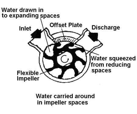
Figure 2 Stabsco Positive Displacement Flexible Impeller Pump

Figure
3 Mechanical Pump Seal
The Stabsco flexible impeller pump in Figure 2 is a positive displacement type. As the flexible impeller lobe passes the offset plate, an expanding space is created which draws in water. The water is carried around the casing in the impeller space, but as the impeller lobe reaches the offset plate, the lobe is bent to squeeze the water into the discharge pipe. The flexible impeller is usually made of neoprene for water, but may be made of other materials for handling oils or fuels.

Figure
4 Jabsco
Flexible Impeller Pump Construction
The shaft may be sealed by packing as shown in Figure 49, or by a mechanical seal as shown in Figure 48. Any air drawn into the pump through suction side seals will break the suction, and stop or slow the flow from the pump. All suction side connections must also be air-tight.
Flexible impeller pumps rely on the fluid to lubricate the impeller and seals. They will be damaged if the pump runs dry. Therefore the pump must be constantly supervised unless an automatic switch, or a method of keeping the pump primed is provided.
Semi-Rotary Hand Pumps
Semi-rotary hand pumps (Figure 5) are often used in small vessels. An easy hand-action produces a substantial flow from the pump.
When the handle is moved in one direction, a side-chamber is squeezed, opening a one-way valve and forcing water into the main chamber.
This displaces the water in the main chamber into the outlet. At the same
time, water is drawn in to fill the other side-chamber.
When the handle is moved in the other direction, water is forced from the
other side chamber into the outlet, while the first chamber is re-filled.


Figure 5 Semi-Rotary Hand Pump
These pumps must be well maintained to prevent them seizing, and to prevent the valves sticking open due to foreign matter. The efficiency of the pump will also be greatly reduced if the seals become worn or damaged.
The handle should never be forced hard over against the stops, as either the rotor or the stops may be damaged.
Strums, Strainers, and Mud Boxes
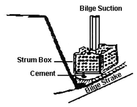
Figure 6 Strum
Strums (Figure 6) are boxes shaped from perforated steel plate.
They are mounted at the suction end of pipes into bilges, holds or engine room, to prevent larger objects entering, clogging, and damaging the bilge system and pumps.
They are usually made so they can be easily dismantled for cleaning. They may be held together with brass bolts, but more often with tongues and split brass pins.
Strainers
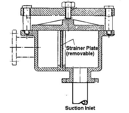
Figure 7 Strainer
Strainers (Figure 7) do a similar job to strums, but must be mounted for easier access, as frequent use means constant cleaning.
The suction inlet pipe goes to the lowest part of the bilge, with sufficient space at the end to let the water get in.
The body and lid are usually of cast iron to provide an air-tight suction seal. Other parts are mild steel. The strainer plate is removable for cleaning.
Mud Boxes
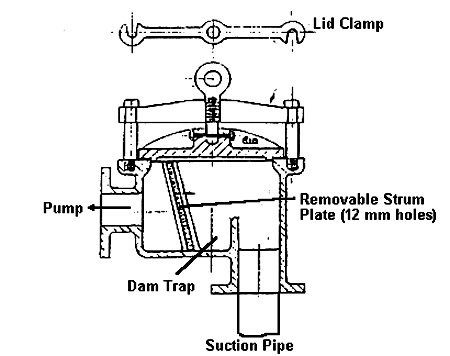
Figure 8 Mud Box
A mud box (Figure 8) is similar to a strainer, but has a dam at the base of the strainer plate.
Solids dropping off the strainer plate are retained in the dam, and prevented from falling back down the suction pipe into the bilge.
Valves
Screw-Down Valves

Figure
9 Screw-down
valve
The screw-down valve (Figure 9) is easy to maintain and repair. It is designed to give full bore delivery. In the non-return version there is no connection between the valve and the spindle. A back-flow into the open valve will force the valve down against the seat, blocking it off. In low pressure applications, there may be insufficient ‘head’ at the inlet to lift a valve which may stick to the seat.
The screw-lift version can be used in these applications, as the valve is forcibly lifted from the seat, but has no non-return function.
(This problem can be overcome by placing a non-return check valve in the line before the screw lift valve.)
The spindle gland can be adjusted with a gland nut, to reduce weepage.
Globe Valve for Overboard Discharges
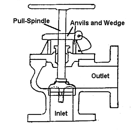
Figure 10 Globe Valve
The pull lift globe valve (Figure 10) for overboard discharges, is opened by a straight pull-lift.
The wedge inserted through a slot in the shaft will hold the spindle raised.
The valve will move freely while water is discharged, but when the water stops flowing, sea pressure will close the non-return valve.
Other Valves in Common Use
Non-Return Check Valves use a pivoting flap (Figure 11) or a spring loaded plunger to allow flow in only one direction. These may be used to prevent back flooding into bilge compartments, etc. Types using flaps must be mounted so gravity will help close the flap when flow stops. Back pressure will hold them closed.
The Gate Valve (Figure 12) uses a tapered ‘gate’ which slides firmly into a seat when closed. The gate valve opens the entire pipe without obstruction when fully opened.
Plug or Ball Cocks (Figure 13) use either a cone shaped plug in a matching seat, or a ball in a matching seat. With the cock turned on, a ‘port’ through the centre of the cone or ball lines up with the pipe. With the cock turned off, the port does not line up and the pipe is blocked.
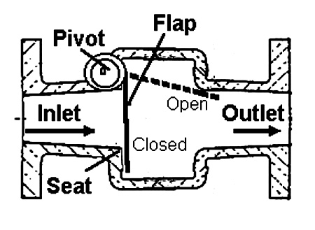
Figure 11 Non-return check valve

Figure 12 Gate valve
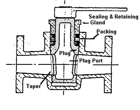
Figure 13 Plug Cock