COMPASS ERROR
(Extracts courtesy of A.N.T.A. publications, Ranger Hope © 2008 www.splashmaritime.com.au)
The courses and bearings laid on a chart are true, but we steer courses and take bearings using a compass.
The compass used in small vessels is more commonly a magnetic compass, although some may be fitted with a gyro compass.
The magnetic compass and the errors involved
The difference between direction as measured by the compass and the true direction as measured on the chart is termed compass error, stated differently:
It is the angular difference between true north and compass north. It is named east or west to indicate the side of true north on which the compass north lies.
Figure 1: Direction of Compass Error
The Compass Error is a combination of two separate and distinct components, namely variation and deviation.
Variation
When influenced only by the earth’s magnetic field, a compass
needle will point towards the earth’s north magnetic pole. This pole is located
somewhere to the north of
Examination of a globe will show that from a position on the East Coast of Australia the compass will point in a direction to the east of true north. This is magnetic north, and the angle between it and true north is called variation. In our case variation is east.
To find the value of variation for any position simply consult the nearest compass rose on a marine chart. The variation will be given for a specified year, together with the rate of change, allowing calculation of variation for any subsequent year. See appendix for variation chart of the world.
Example
Chart Aus 823 gives the following information on the compass rose to the south of St Bees Island:
Mag Var 8°40’E (1979) Increasing about 2’ annually.
In 1997 the variation will have increased by 2’ each year for 18 years, a total of 36. Adding this to 8°40’ we find that the variation for 1997 is 9°16’E.
Deviation
In the unlikely event that a vessel is constructed entirely from non magnetic materials and has no electronics close to the compass, variation is the only error which will need to be accounted for. In all other cases the vessel and/or its equipment will create magnetic fields of their own. Some of these will be built into the vessel on the slip, others will change as the vessel moves around within the influence of the earth’s magnetic field.
The compass adjuster is usually able to reduce the effect of the vessel’s magnetic fields, but the causes are so complex that it is inevitable that some effects remain. For the ship’s compass to work at all the effect of the ship’s magnetism must be less that the force of the earth’s magnetic field.
To illustrate the effect of the vessel’s own magnetic field, imagine a vessel on which the compass needle is attracted towards the stern. When that vessel is heading towards magnetic north the effect of the pull towards the stern is to reduce the directive force at the compass but not to deflect it from magnetic north. As the vessel turns onto easterly headings the compass needle is deflected towards the stern i.e. towards west. When the vessel heads west the compass needle is deflected to the east. There will be no deflection when the vessel heads south, but an increase in directive force.
This deflection of the compass away from magnetic north is called deviation. As with variation it is named East or West and the value will change according to the ship’s heading. A deviation card is produced by the compass adjuster when the vessel is first commissioned and at intervals throughout its life. It is displayed close to the compass position.
The relationship between compass, magnetic and true courses and bearings is shown in the following diagram.

Figure 2: Relationship between Compass, magnetic and truc courses and bearings.
Rules for applying Variation and Deviation.
To avoid drawing diagrams every time variation and deviation are applied, a number of memory aids have been developed to clarify the rules of application:
Television Makes Dull Company
(T V M D C) reminds us that to true we must apply the variation to find magnetic, and to this we apply deviation to arrive at compass (course or bearing).
If we start with a compass bearing and wish to convert it to true the order of operation is reversed (C D M V T).
Having decided the correct order in which to apply variation and deviation, we need to know whether the correction should be added or subtracted. This may be decided using the word:
C A D E T
This simply indicates that to get from compass to true (the end points) we Add East.
Given that we add east (deviation or variation) it follows that we must subtract west (deviation or variation).
It also follows that if we add east to get from compass to true, we should add west when going from true to compass.
A simple layout for applying these rules is shown on the next page.
Compass Error
If we expect to take several bearings whilst steering the one steady course it makes good sense to arrive at a single correction to apply to all those bearings. Remembering that the variation remains effectively the same whilst operating in one area, and that deviation only changes when we change course, we can find the compass error for the course being steered and apply that to all bearings taken whilst on that course.
Example:
We are steering 076°(C). The deviation from the deviation card for 076° is 3°W and the variation from the chart is 11°E. The compass error (combined variation and deviation) is therefore 8°E. Since we are converting compass bearings to true we add East (CADET).
Therefore whilst steering 076°(C) add 8° to any compass bearing to convert it to true.
Simple layout for applying variation and deviation:
| 1. Changing from compass to true. |
|
| Compass Course |
215° (C) |
|
Deviation |
6° W (between 210 & 220 in dev. table below) |
| Magnetic Course |
209° (M) (add E so subtract W) |
| Variation |
11° E (from chart) |
| True course |
220° (T) (add E) |
| 2. Changing from true to compass |
|
| True Course |
220° (T) |
| Variation |
- 11° E (from chart) |
| Magnetic Course |
209° (M) (from T to C subtract E) |
| Deviation |
+ 5.5° W (from deviation table for 210) |
| Compass course |
214.5 ° (C) (add W) |
For most practical purposes this compass course is sufficiently accurate, but to be strictly correct we should re-enter the deviation table with a Compass Course of 214°, rather than the magnetic course of 209°. In this case deviation would be 6°W and the total working as follows:-
| True Course |
220° (T) |
| Variation |
11° E |
| Magnetic Course |
209° (M) |
| Deviation |
5.5° W (Deviation for 214° = 6° W) |
| Compass Course |
215° (C) 214.5 (C) Compass Course |
The difference is rarely likely to be great, but beware a deviation card which indicates rapid changes in deviation.
When working with bearings the same lay-out is followed but remember that the deviation table is entered with Ship’s Head, Not Bearing.
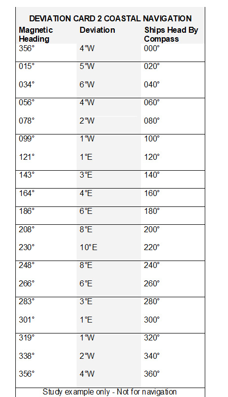
Deviation Table for examples

The Gyro Compass
Although it is popularly believed that the gyro compass indicates true North, this is not necessarily the case.
The gyro is subject to course, speed and latitude errors. These are kept to the minimum by input corrections.
The gyro error is rarely more than one or two degrees for a correctly maintained gyro.
To avoid confusion with magnetic errors, gyro error is named high (H) or low (L).
Gyro error is named high when the gyro course or bearing is higher than the true course or bearing. Therefore high error must be subtracted from the gyro reading to obtain the true reading. The opposite applies to low error.
Example
Gyro error is known to be 2° high. The true course to be steered is 076°. What is the gyro course?
True Course 076°
Gyro error 2° H
Gyro Course 078°
A bearing taken with the same gyro gives 246° (G). What is the true bearing?
Gyro bearing 246°
Gyro error 2° H
True bearing 244°
Relative Bearings
When bearings are taken using a pelorus, or by radar with an unstabilised display (ship’s head up), the bearing taken will be measured relative to the ship’s head, rather than north.
Such a relative bearing must be applied to the true ship’s head to arrive at a true bearing for plotting on the chart. This will entail changing the compass course to true and then adding the relative bearing (if in 360° notation).
Using 360° notation is now normal practice, but if the relative bearing is a given number of degrees Green (starboard) then it is also added. If the relative bearing is a given number of degrees Red (port), then it is subtracted. In the example below the relative bearing would have been Red 86°. To subtract this from the true course it would have been necessary to first add 360°. The answer is again 352° (T).
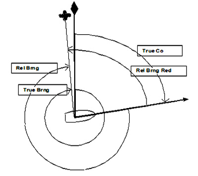
Figure 3: Relationship between True and Relative Bearings
| Example for Relative Bearing Working |
|
| A vessel is steering 073° (C) |
Compass 073° (C) |
| Deviation is 5.5° E |
Magnetic 078.5° (M) |
| Variation 9° E |
True 087.5° (T) |
| The relative bearing of Edward Island Light is |
274° (Rel) |
| What is the true bearing of Edward Island Light? |
|
| Rel. Brng. |
274° (R) |
| True Brng. |
001.5° (T) |
We now have to consider the checking of a Deviation Card, and keeping a record book. Samples of deviation cards are at the end of this text.
To find the Compass Error by Observation
Every opportunity to check the accuracy of your compass and (deviation card) must be taken while within coastal observations of charted objects. If there is some doubt as to the accuracy of the deviation card, or in any case as a periodical check, the deviation can be determined by one of two simple methods :
By Transit Bearings
When two well charted objects are in transit a compass bearing is taken.
The true bearing is taken from the chart using parallel rulers.
Comparison of the compass bearing and the true bearing gives the compass error.
A transit bearing when two or more objects lie on the same line, as in Figure 4.
If the deviation is required it is calculated by applying the charted variation to the compass error.
Try checking the compass error using an azimuth circle on your compass and a Transit Bearing. A more difficult one is using a pelorus for a Relative Bearing, then converting this to a Compass Bearing.
Ask the Master to show you. Then practice.
Example:
In this case a bearing has been taken of “Leading Lts 045°“
True Bearing 045°
Compass Bearing 048°
Compass Error 3° W
Variation 11° E
therefore Deviation 8° E. As this does not agree with the deviation card as above, checks must be made to see if magnetic objects have been temporarily left near the compass, and if not, then the compass should be swung by a compass adjuster at the earliest opportunity..

Figure
4: Compass Error by Transit using a Azimuth Circle.
(Drawing by courtesy of Small Ships Manual)
In the second method you require to know your exact position, this can be obtained by :-
A. Corrected G.P.S.
B. Ranges from radar
C. Ranges from Vertical Sextant Angles
The object should be on the chart and well distanced from the vessel.
By Bearing from a Known Position
When the vessel’s position is accurately fixed, a compass bearing may be taken of a well charted and distant object, say a tower (as in Figure5).
The true bearing can again be taken from the chart using parallel rulers. Calculation made as above.
Any small change in the vessel’s position whilst swinging will have a negligible effect on the true bearing if the chosen object is sufficiently distant.
Figure 5: Compass Error from a known position
Example:
True bearing 050°
Compass bearing 033°
Compass error 17° E
Variation 11° E
Deviation 6° E
As this does not agree with the deviation card as above, checks must be made to see if magnetic objects have been temporarily left near the compass, and if not, then the compass should be swung by a compass adjuster at the earliest opportunity..A record of Compass Errors and Deviation should be kept in a Compass Record Book.
Samples of Deviation Cards from different vessels
Deviation Card 1

Deviation Card 2
Deviation Card 3

For all practical purposes it is unlikely to be possible to steer a small craft with accuracy of 0.5°. Calculations to 1° degree will therefore be sufficient.