MATHS FOR MARINERS
Ranger Hope©2014 - View as a Pdf file
This text is provided
for research and study only on the understanding that users exercise due care
and do not neglect any precaution which may be required by the ordinary
practice of seamen or current licensing legislation with respect to its use. No copying is permitted and no liability is
accepted resulting from use.
Ranger Hope © 2014
Introduction
1.1 Logic, attributes and sets
1.2 Number, value and counting
1.3 Numbering systems and number base
1.4
Scientific
notation - exponents and roots
2.1 Addition, subtraction, multiplication and
division
3.1 International System of Units
3.2 Derived units and formulas
Chapter 4: Shape, size and capacity of tanks
4.4 Pumps and flow rate capacity
Chapter 5:
Calculating fuel requirements for a voyage
5.2 Specific fuel
consumption and fuel coefficients
Chapter 6: Calculating a vessel’s draught and trim
6.2 Moments and longitudinal trim
6.3 Moments
and transverse trim
7.2 Strength of rope, wire and chain
7.4 Blocks,
tackles and purchases
Chapter 8: Structure and strength
Chapter 10: Electrical calculations
Introduction
This text is intended for those studying to begin a maritime career. It aims to jog the memory of those who may have long since left school and whose arithmetic, algebra, measure and geometry skills could be bettered.
This is a reference source for formulas and methods required to solve mathematical problems common in the mariner’s workplace. Although each section begins with basics, it is not intended to be read from start to finish. However, thumbing back to an earlier chapter may be helpful in refreshing some underpinning concepts.
I learnt arithmetic at school entirely by the rote method of daily chanting the times tables. But as schooling progressed I became entirely confounded by the mystery of slide rules, logarithms and calculus. I never really understood logic or numbers and like many I have survived with imperfect memories and a reliance on calculators. So this text is also a personal journey of re-learning of how to crawl before running. The first chapter that deals with the pre-mathematics skills of logic, sorting, base and numbering systems is provided for those who may also have been dozing at the back of the class.
Chapter 1: Logic
1.1. Logic, attributes and sets
Definitions
Logic refers to consistent rules where actions have predicable results.
Geometry describes
how to draw shapes and defines the mathematical rules (relationships)
concerning their construction.
Mathematics or maths describes the logical processing information using numbers.
Algebra enables logical solutions by balancing (equating) a set of calculations with a known value against one with a partially known value.
An attribute is that observable feature of a thing that makes it similar to or dissimilar from another thing. It defines what makes an individual.
To sort is to make collections (sets) of individuals determined by their common attributes.
A set is a group (collected) of individuals with one or more common attributes.
A number is a sequenced symbol used to represent an individual unit or the quantity of members of a set. The symbols we commonly use are derived from those of ancient India and Arabia. Those ancients invented the nine basic symbols of 1 representing an individual finger, 2, 3, 4, 5, 6, 7, 8, 9 representing subsequent sets of fingers (digits) and symbol 10 for the full set of fingers.
The value of a number is the size of the collection of individuals that it represents. An individual has a value of one unit.
To count is to use a systematic process to find the value of a collection. Methods have included such as using the fingers, tally marks, counters, number symbols or electronic calculators.
To process is to apply a logical rule to change an individual or to change the members of a set. In logical processes an action (a cause) has a consistent result (an effect). This predictability enables mathematics to be used to provide workplace solutions other than by trial and error.
Basic calculation is to use counters or numbers in the processes of addition (add), subtraction (take away), multiplication (times) and division (share).
Sets and sorting
To understand our world we seek consistent rules where actions have predicable results – we look for a cause leading to a repeatable affect – we apply logic.
Our world is filled with many things - some have similar and some dissimilar features. An attribute is a defining feature of a thing. The picture below shows a collection of things that have the common attribute of being coloured wooden blocks but differing attributes of colour, shape, thickness or size. Attributes define what makes a thing an individual. For instance, there is only one circle that is red, thick and large.
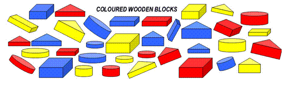
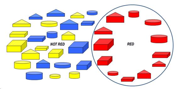
Attributes allow us to compare one thing with another, make rules to classify them into logical collections and sort them into sets (groups of individuals with similar attributes). The chaotic pile of blocks above can be logically sorted and made sense of in a number of ways. All the red blocks have been selected to form a red set, leaving a remainder of those that do not have the red attribute (are yellow or blue).
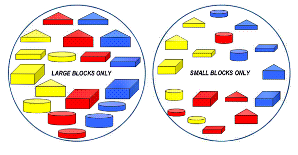
However we could just as easily have created different sets by using different attributes to separate the wooden blocks into like groups. The logical rule we have used below is to select for each set on the basis of size only – large or small attribute.
Or we could have created other sets by using other attributes of the wooden blocks. The logical rule we have used below is to select on the basis of thickness only – thin or thick attribute.
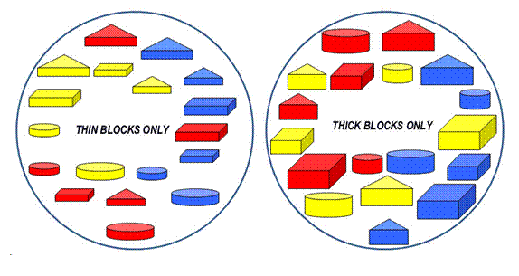

Other sets are created by using the other attributes of colour or shape.
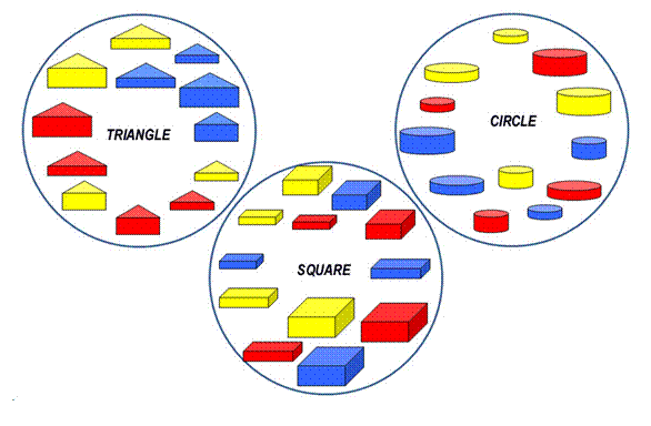
In summary, attributes define what makes an individual. For instance, there is only one circle that is red, thick and large. Attributes also define the members that can make up a logical group so enabling set size to be compared. For instance, the size of each shape set above compares to a set of 10 of our fingers plus 2 of our toes.
1.2 Number, value, and counting
A number is a concept that represents the value of a set (collection). The number symbols used today are derived from those developed in ancient India and Arabia.
1 represents a finger or individual (a digit), 2, 3, 4, 5, 6, 7, 8, 9 represent the quantity or sequence of digits and 10 represents a full set of digits counted on both hands.
The value of a number describes the quantity of individuals in collection or the sequence of an individual’s position within a set - whether it is first, second, third etc.
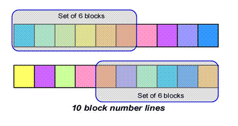
Shown above are quantities of six block sets that have been separated from the number lines (each of ten blocks). Note that though both top and bottom sets contain 6 blocks, the blocks themselves are different. Number 6 is not the exclusive name of either set, but a description of a set’s attributes - they each contain six blocks.
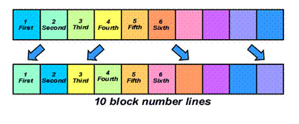
Shown above are two number line sequences where the blocks have been rearranged. The name of top row yellow block number 4 is not a constant. If it is re-positioned in the bottom row then it is renamed as block number 3.
Shown below are two number line sequences where the blocks have been rearranged. This time the lower line has been reversed. Unlike the previous number lines, we can give each block a constancy of name if we apply a constancy rule - to reverse the starting point of our sequence from left to right, to right to left.
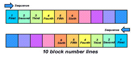
It is natural to use numbers as names from an object’s place in a group, such as 1st finger, 2nd finger and 3rd finger. However, name and number are different ideas. Constancy of number relates to the logical rule not the name temporarily given to an object. An ability to trust in learnt mathematical rules and before relating back to real objects is needed in order to efficiently count, process and eventually to calculate.
To count is to use a systematic process to find the value of a collection. Methods include using the fingers, measuring, striking tally marks, use of counters, number lines, mental arithmetic, tables and electronic calculators.
Tally - an historical perspective
With the fingers on one hand we can communicate the idea of up to five things. Counting is seen in ancient tally marks scratched onto clay tablets to represent flocks of sheep or chalked as tally marks of present day stevedores. As each collection is gathered (recorded as groups of scratches) the marks are slashed through to reckon a total - below records two sets of 5 sheep and another 4.
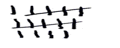
Tallying requires only observation skills to accurately strike the marks, unlike processing (to apply a logical rule predicting a result). Processing is explained below.
Processing
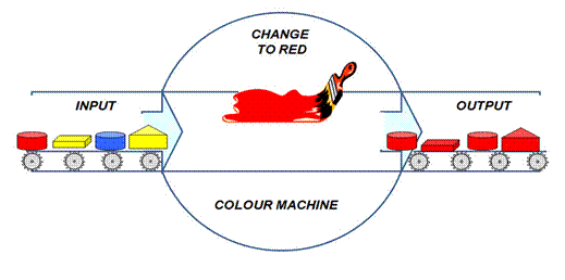
Once you have defined the attribute/s of an individual, a rule can be invented to process or logically change that attribute/s. The processing rule used by the colour machine shown below is to paint (change to red) anything passed through the input to the output. All other attributes remain unchanged (the shape, size and thickness).
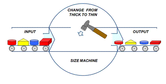
However we could just as easily have created different output by changing the processing rule. The rule used by the logical thickness machine shown below is to hammer (change to thin) anything passed through the input to the output. All other attributes remain unchanged (the shape, size and colour).
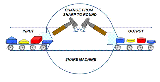
Or we could just as easily have created different output by another processing rule. The rule used by the logical rounding machine shown below is to hammer (change to round) anything passed through the input to the output. All other attributes remain unchanged (the thickness, size and colour).
Similarly the rule used by the logical copy machine shown below is to make two additional copies of anything passed through the input to the output. All attributes remain unchanged as the additional units are exact copies (clones).
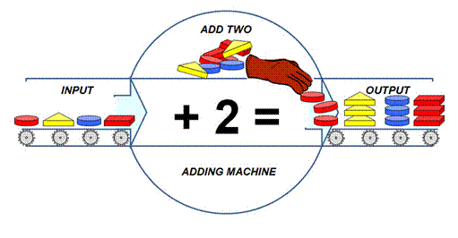
We can represent this adding machine as a sum using the processing symbols of + for plus (adding) and = for equals (the result). For
instance, for each block inputted:
1 + 2 = 3
1 (red square) + 2
(red squares) =
3 (red squares)
1 (blue circle) + 2
(blue circles) =
3 (blue circles)
1 (yellow triangle) + 2
(yellow triangles) = 3 (yellow triangles)
1 (red circle) + 2 (red circles) =
3 (red circles)
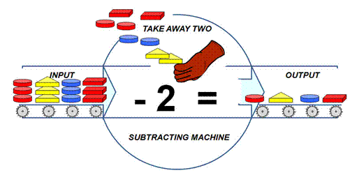
Likewise the removing machine above that takes away two of anything passed through it can be represented by a subtraction using the symbols - for subtract (take away) and = for equals (the result). For instance, for each group of blocks inputted:
3 - 2 = 1
3 (red squares) - 2
(red squares) =
1 (red square)
3 (blue circles) - 2
(blue circles) = 1
(blue circle)
3 (yellow triangles) - 2
(yellow triangles) = 1 (yellow triangle)
3 (red circles) - 2
(red circles) =
1 (red circle)
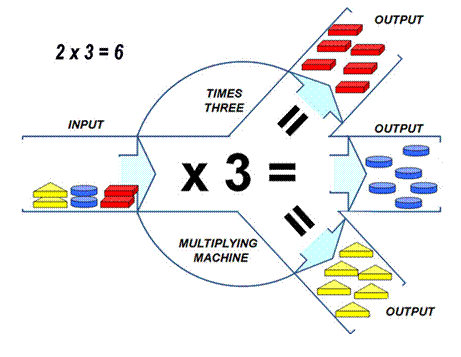
The logical multiplying machine shown below that trebles anything passed through it can be represented by a multiplication using the symbols x for multiply (times) and = for equals (the answer). For instance, for each block inputted:
1 x 3
= 3
2 (yellow triangles) x 3 = 6 (yellow triangle)
2 (blue circles) x 3 = 6 (blue circle)
2 (red squares) x 3 = 6 (red square)
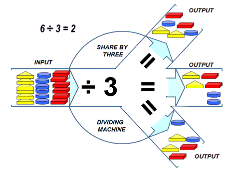
The logical sharing
machine shown below can be represented by a division using the symbols ÷
for divide (share) and = for equals
(the answer). For instance, for each group of blocks inputted:
Tables and examples
|
Add + |
Take away - |
Times x |
Share ÷ |
|
|
1 + 1 = 2 |
1 - 1 = 0 |
5 - 5 = 0 |
1 x 1 = 1 |
1 ÷ 1 = 1 |
|
1 + 2 = 3 |
2 - 1 = 1 |
6 - 5 = 1 |
|
|
|
1 + 3 = 4 |
3 - 1 = 2 |
7 - 5 = 2 |
2 x 2 = 4 |
2 ÷ 2 = 1 |
|
1 + 4 = 5 |
4 - 1 = 3 |
8 - 5 = 3 |
2 x 3 = 6 |
4 ÷ 2 = 2 |
|
1 + 5 = 6 |
5 - 1 = 4 |
9 - 5 = 4 |
2 x 4 = 8 |
6 ÷ 2 = 3 |
|
1 + 6 = 7 |
6 - 1 = 5 |
|
2 x 5 = 10 |
8 ÷ 2 = 4 |
|
1 + 7 = 8 |
7 - 1 = 6 |
6 - 6 = 0 |
|
10 ÷ 2 = 5 |
|
1 + 8 = 9 |
8 - 1 = 7 |
7 - 6 = 1 |
3 x 2 = 6 |
|
|
1 + 9 = 10 |
9 - 1 = 8 |
8 - 6 = 2 |
3 x 3 = 9 |
3 ÷ 3 = 1 |
|
|
|
9 - 6 = 3 |
|
6 ÷ 3 = 2 |
|
2 + 2 = 4 |
2 - 2 = 0 |
7 - 7 = 0 |
|
9 ÷ 3 = 3 |
|
2 + 3 = 5 |
3 - 2 = 1 |
8 - 7 = 1 |
4 x 2 = 8 |
|
|
2 + 4 = 6 |
4 - 2 = 2 |
9 - 7 = 2 |
|
|
|
2 + 5 = 7 |
5 - 2 = 3 |
|
5 x 2 = 10 |
4 ÷ 4 = 1 |
|
2 + 6 = 8 |
6 - 2 = 4 |
8 - 8 = 0 |
|
8 ÷ 4 = 2 |
|
2 + 7 = 9 |
7 - 2 = 5 |
9 - 8 = 1 |
|
|
|
2 + 8 = 10 |
8 - 2 = 6 |
9 - 9 = 0 |
|
5 ÷ 5 = 1 |
|
|
9 - 2 = 7 |
|
|
10 ÷ 5 = 2 |
|
|
|
|
|
|
|
3 + 3 = 6 |
3 - 3 = 0 |
10 - 1 = 9 |
|
|
|
3 + 4 = 7 |
4 - 3 = 1 |
10 - 2 = 8 |
|
|
|
3 + 5 = 8 |
5 - 3 = 2 |
10 - 3 = 7 |
|
|
|
3 + 6 = 9 |
6 - 3 = 3 |
10 - 4 = 6 |
|
|
|
3 + 7 = 10 |
7 - 3 = 4 |
10 - 5 = 5 |
|
|
|
|
8 - 3 = 5 |
10 - 6 = 4 |
|
|
|
|
9 - 3 = 6 |
10 - 7 = 3 |
|
|
|
|
|
10 - 9 = 2 |
|
|
|
4 + 4 = 8 |
4 - 4 = 0 |
10 - 9 = 1 |
|
|
|
4 + 5 = 9 |
5 - 4 = 1 |
|
|
|
|
4 + 6 = 10 |
6 - 4 = 2 |
|
|
|
|
|
7 - 4 = 3 |
|
|
|
|
5 + 5 = 10 |
8 - 4 = 4 |
|
|
|
|
|
9 - 4 = 5 |
|
|
|
|
Plus |
Minus |
Multiply |
Divide |
|
1.3 Numbering systems and number base
All numbering systems employ a base set of symbols. The commonly used, base ten (1₁₀), imitates a full set of fingers (our digits). Combinations of the nine symbols of 1, 2, 3, 4, 5, 6, 7, 8, 9 (representing each value) and 0 (representing zero or tens of units) can represent any number. Two sets are then 20, three 30, and so on.
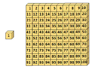
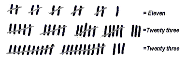
Others bases are used when convenient, such as base two or binary system used in computer code. Below the tally marks show eleven marked in sets of two (Base ₂) and twenty three marked off in both sets of five (Base ₅) and in sets of ten (Base ₁₀).
Base Five (1₅)
Base five numbering system imitates a set of fingers on one hand only and (example below) uses combinations of four symbols and a zero to express all numbers.
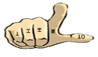
In base₅, we have an individual digit, or we can build a square or a cube of with groups of individuals. The total value of each pile is logically numbered as shown below using the invented symbols of slashes on sticks.
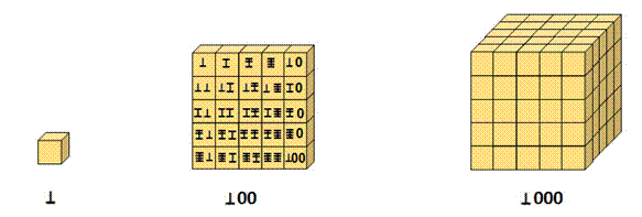
In base₅ using our invented symbols we can express sets, values and a number to represent each value as: |
||
|
Base Sets |
Digits Value |
Number Symbol |
|
Two sets are written (digits of both hands) |
|
|
|
Three sets are written |
|
|
|
Five sets are written |
|
|


However, we could have used the Indus-Arabic symbols of 1, 2, 3, 4, and 0 to express our numbers. To represent the thumb a zero is now partnered with symbol 1 so the number symbol of 10 now represents a full set of five digits.
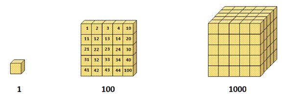
Take care that you only use one base system at a time, as each base attributes a different value to its number symbols. Base₅ number 1000₅ does not have the same value as Base₁₀ number 1000₁₀. We use base₁₀ so universaly that we rarely annotate with the base system symbol or think about the bases of our numbering systems.
In base five using conventional Arabic symbols we can express sets, values and a number to represent each value as: |
||||
|
Base Sets |
Digits Value |
Base
5 |
Base
10 |
|
|
Two sets are written (digits of both hands) |
|
20 |
10 |
|
|
Three sets are written |
|
30 |
15 |
|
|
Five sets are written |
|
100 |
25 |
|
Base Two (1₂)
The Base-two number system (binary numeral system) is used for computer code because electronic switches can easily read and store two states, on or off (twin voltage may be used by some systems). To these states are given the symbols 1 and 0.
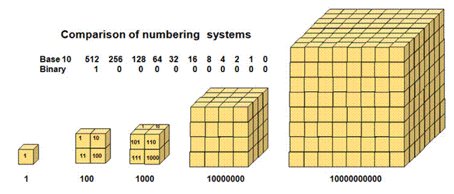
A conversion from a binary number’s value to its equivalent base₁₀ value can be made with the table shown above. Binary values are derived from sets of two and progressive multiples. These values of 64, 512, 1028, and 2056 megabytes are used to specify the Random Access Memory power of a computer’s micro-processor.
1.4 Scientific notation - integral exponents and roots
Understand Chapter Two before reading this section. To reduce the zeros required to write the very large and very small numbers that engineers use, a short hand termed of numbers to a power (integral exponents) is used. These symbols are written by the right hand top of a number. Shown in the examples below, ten is the number and the power is to two and to three, commonly called squared or cubed.
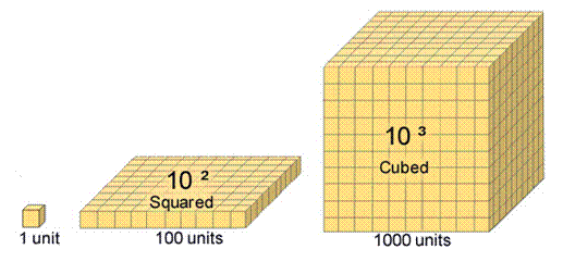
Described as ten squared and written as 10² is calculated 10 x 10 =
100
Described as ten cubed and written as 10³ is calculated 10 x 10 x 10 = 1000
Similarly,
Ten to the fourth power is 10⁴ is calculated as 10 x 10 x 10 x 10 = 10,000
Ten to the fifth power is 10⁵ is calculated as 10 x 10 x 10 x 10 x 10 = 100,000
Any number can be written to a power as in the examples below:
Three squared is written as 3²
and calculated as 3 x 3 = 9
Four cubed is written as
4³ and calculated as 4 x 4 x 4 = 32
Five to the fourth power is 5⁴ and calculated
as 5 x 5 x 5 x 5 = 625
Six to the fifth power is 6⁵ and calculated
as 6 x 6 x 6 x 6 x 6 =1296
When calculating with multiples of 10, the power defines the number of zeros (0):
Ten to the power of two has two zeros (100 = a hundred),
Ten to the power of three has three zeros (1000 = a thousand)
Ten to the power of six has six zeros (1,000,000 = a million)
Ten to the power of twelve has twelve zeros (1,000,000,000,000 = a billion)
* Note France & US use
one thousand times one million to define a US billion)
For instance, below both numbers can be written to a power.
257 =
2.57 x 100 =
2.57 x 10²
2,570,000 = 2.57 x 1,000,000 =
2.57 x 10⁶
The
convenience of exponents is further seen in expressing the concept of infinity
(going on forever without end). The simple expression of ten to the power of
infinity as below would otherwise require an unending task of writing 0 after 0
without end.

Exponents also simplify
otherwise tedious calculations
and lessen the chance of error in the positioning of a decimal point. As below,
exponents can be written as powers of ten or as decimals by use of the minus
sign.
10⁵ =
100,000
10ˉ⁵ = 0.00001
10⁴ = 10,000
10ˉ⁴ = 0.0001
10³ =
1000 10º =
1 10ˉ³ = 0.001
10² =
100
10ˉ² =
0.01
10¹ =
10 10ˉ¹ =
0.1
For consistency using decimal place, the following rule is used:
Place the decimal point immediately to the right of the first non zero digit.
Compare the number of digits between the new decimal point and the original.
This number is the value of the exponent.
0.00257 = 2.57
x 0.001 =
2.57 x 10ˉ³
0.257 = 2.57
x 0.1 =
2.57 x 10ˉ¹
Roots (inverse powers)
The root of a number is that value that when multiplied by itself for specified repeat instances will be equal to the number. It is the inverse (reversed process) of a power, for instance:

All numbers have a root as in the examples below:

Some numbers roots and number are the same, for example numbers 0 and 1 whose roots are 0 and 1:

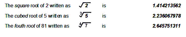
The roots of some numbers are called irrational numbers because they never resolve as a whole number, for example the roots of 2, 5 and 7:
Fractional exponents
Some engineering problems require solving problems that involve the use of fractional powers. While these are easily solved following the stepped instructions with a scientific calculator, the following examples are shown in explanation.
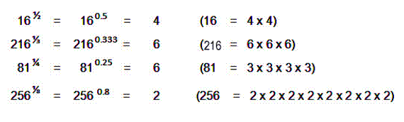
Exponents can be written as fractions. In these
cases exponent ½ indicates the power of 1 and square root of the number.
Similarly exponent ⅓ indicates
the cube root, ¼ the fourth root, ⅛ the eighth root, and so on.
In mathematical
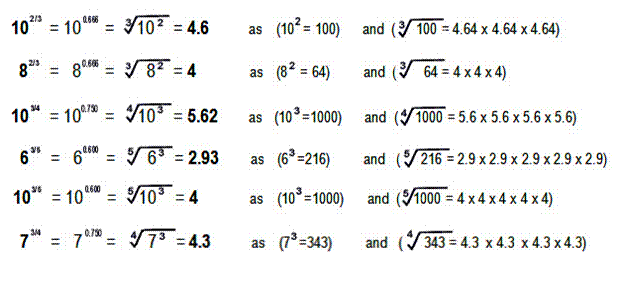
terms, the fractional exponents indicate that the numerator will raise a number
to that power and the denominator takes it to that root.
Chapter 2: Calculations
Using the fingers to count or share more than ten units is difficult. This section describes other ways to solve arithmetic problems when using base ten, the commonly used numbering system. (See more about other bases in Section 1.3).
The four
principle operations are denoted by symbols (signs) and are named:
+ Plus to add or to sum by addition
- Minus to subtract or to take away by a subtraction
x Times to multiply or times by a multiplication
÷
Divide by to divide or to share by a division
A calculation is
a arithmetical problem with its solution (its answer). Calculations can
be expressed (written down in maths
shorthand) using an equation. The
problem is written on the left, the solution on the right with an equals symbol (=) between them. In a
balanced equation, each side of the equals sign must have the same total. (See
more on equations and algebra in Section
2.4). Simple equations are
shown below:
1 +
1 = 2 or
3 - 1 = 2 or
2 x 2 = 4 or
4 ÷ 2 = 2
1 plus 1 equals 2 3 minus
1 equals 2 2 times 2 equals
4 4 divide by 2 equals 2
2.1 Addition, subtraction, multiplication and
division
Various methods used to find solutions are descibed below.
Using the Number Line
method and mental arithmetic
A scale or ruler is
a number line when used as a visual
aid in addition (counting out), subtraction (finding a remainder), division
(sharing) and multiplication (times).
In your mind cut
the stick below into 12 slices and then count the slices out to share with ten
persons. Ten can be evenly shared but two slices are left over. We have used
the number line below to record our
sharing and the remainder that was left.

What we have done can be expressed by the
equations:
Addition
Subtraction
1+1+1+1+1+1+1+1+1+1=10 shared orange 12
-10 = 2 remainder brown
Multiplication
and division could also be visualised using the number line. The 12 slices
could be counted out in sets
(See 1.1 Sets and sorting):
2 sets
of six slices can be written as
2 x 6 = 12
or 12 ÷ 6 = 2
3 sets
of four slices can be written as 3
x 4 = 12 or 12 ÷ 3 = 4
4 sets
of three slices can be written as 4 x 3 = 12 or 12 ÷ 4 = 3
6 sets
of two slices can be written as 6 x 2 = 12 or 12 ÷ 2 = 6
While this scale
is marked in twelve units, each unit could be further divided into 8 sub units
to solve more complex problems (by counting up the units), as below:
1 units x 8 sub-units = 8 sub-units
4 units x 8 sub-units = 32 sub-units
12 units x 8 sub-units = 96
sub-units

The number line
works well for small numbers but as it relies on counting out every unit it is
slow for complex problems.
Using the Times Tables
method
Fast solution to
maths problems can be looked up or learnt as the times tables below. (also see addition
tables Section1.2). They can also be used to find division
solutions. It can be seen that one side of each equation is equal to the other.
For example, in the times x 4 table
equation of below 8 x 4 = 32, it is also true that 32 shared
among 4 will have a solution of 8.
8 x 4 = 32 or 32 ÷ 4 = 8
|
Times x 1 |
Times x 2 |
Times x 3 |
Times x 4 |
Times x 5 |
Times x 6 |
|
1 x 1 = 1 |
1 x 2 = 2 |
1 x 3 = 3 |
1 x 4 = 4 |
1 x 5 = 5 |
1 x 6 = 6 |
|
2 x 1 = 2 |
2 x 2 = 4 |
2 x 3 =
6 |
2 x 4 = 8 |
2 x 5 = 10 |
2 x 6 = 12 |
|
3 x 1 = 3 |
3 x 2 = 6 |
3 x 3 = 9 |
3 x 4 = 12 |
3 x 5 = 15 |
3 x 6 = 18 |
|
4 x 1 = 4 |
4 x 2 = 8 |
4 x 3 = 12 |
4 x 4 = 16 |
4 x 5 = 20 |
4 x 6 = 24 |
|
5 x 1 = 5 |
5 x 2 = 10 |
5 x 3 = 15 |
5 x 4 = 20 |
5 x 5 = 25 |
5 x 6 = 30 |
|
6 x 1 = 6 |
6 x 2 = 12 |
6 x 3 = 18 |
6 x 4 = 24 |
6 x 5 = 30 |
6 x 6 = 36 |
|
7 x 1 = 7 |
7 x 2 = 14 |
7 x 3 = 21 |
7 x 4 = 28 |
7 x 5 = 35 |
7 x 6 = 42 |
|
8 x 1 = 8 |
8 x 2 = 16 |
8 x 3 = 24 |
8 x 4 = 32 |
8 x 5 = 40 |
8 x 6 = 48 |
|
9 x 1 = 9 |
9 x 2 = 18 |
9 x 3 = 27 |
9 x 4 = 36 |
9 x 5 = 45 |
9 x 6 = 54 |
|
10 x 1 =10 |
10 x 2 = 20 |
10 x 3 = 30 |
10 x 4 = 40 |
10 x 5 = 50 |
10 x 6 = 60 |
|
Times x 7 |
Times x 8 |
Times x 9 |
Times x 10 |
Times x 11 |
Times x 12 |
|
1 x 7 = 7 |
1 x 8 = 8 |
1 x 9 = 9 |
1 x 10 = 10 |
1 x 11 = 11 |
1 x 12 = 12 |
|
2 x 7 = 14 |
2 x 8 = 16 |
2 x 9 = 18 |
2 x 10 = 20 |
2 x 11 = 22 |
2 x 12 = 24 |
|
3 x 7 = 21 |
3 x 8 = 24 |
3 x 9 = 27 |
3 x 10 = 30 |
3 x 11 = 33 |
3 x 12 = 36 |
|
4 x 7 = 28 |
4 x 8 = 32 |
4 x 9 = 36 |
4 x 10 = 40 |
4 x 11 = 44 |
4 x 12 = 48 |
|
5 x 7 = 35 |
5 x 8 = 40 |
5 x 9 = 45 |
5 x 10 = 50 |
5 x 11 = 55 |
5 x 12 = 60 |
|
6 x 7 = 42 |
6 x 8 = 48 |
6 x 9 = 54 |
6 x 10 = 60 |
6 x 11 = 66 |
6 x 12 = 72 |
|
7 x 7 = 49 |
7 x 8 = 56 |
7 x 9 = 63 |
7 x 10 = 70 |
7 x 11 = 77 |
7 x 12 = 84 |
|
8 x 7 = 56 |
8 x 8 = 64 |
8 x 9 = 72 |
8 x 10 = 80 |
8 x 11 = 88 |
8 x 12 = 96 |
|
9 x 7 = 63 |
9 x 8 = 72 |
9 x 9 = 81 |
9 x 10 = 90 |
9 x 11 = 99 |
9 x 12 =108 |
|
10 x 7 = 70 |
10 x 8 = 80 |
10 x 9 = 90 |
10 x 10 =100 |
10 x 11 =110 |
10 x 12 =120 |
Using Short calculations
- simple addition, subtraction, multiplication, division
Short
addition calculations are
written as columns to sum in an answer box below:
|
UNIT |
UNIT |
UNIT |
UNIT |
|
5 |
4 |
7 |
6 |
|
+3 |
+5 |
+2 |
+3 |
|
8 |
9 |
9 |
9
|
|
|
|
|
|
Lists can also be added. Note - for numbers of 10
or more the first step is to add the Units column (right hand in blue below), and the second step the left hand Tens:
|
|
|
TENS UNITS |
TENS UNITS |
|
3 |
4 |
4 |
1 2 |
|
2 |
1 |
1 2 |
1 3 |
|
+3 |
+2 |
+1
2 |
+1 0 |
|
8 |
7
|
2 8 |
3 5 |
Check your progress addition -try these sums yourself:
|
2 |
4 |
5 |
2 |
|
1 |
1 |
1 |
3 |
|
+2 |
+2 |
+3 |
+5
|
|
? |
?
|
? |
?? |
|
|
|
|
|
|
5 |
6 |
12 |
21 |
|
5 |
10 |
14 |
13 |
|
+5 |
+12 |
+10 |
+15 |
|
?? |
?? |
?? |
?? |
|
|
|
|
|
|
Answers addition - as below: |
|||
|
2 |
4 |
5 |
2 |
|
1 |
1 |
1 |
3 |
|
+2 |
+2 |
+3 |
+5 |
|
5 |
7
|
9 |
10 |
|
|
|
|
|
|
5 |
6 |
12 |
21 |
|
5 |
10 |
14 |
13 |
|
+5 |
+12 |
+10 |
+15 |
|
15 |
28
|
36 |
49 |
Short subtraction calculations can also be written in the
same format as below. Note - for numbers of 10 or more the first step is to add
the Units column (U), and the second step
adds the Tens column (T):
|
|
|
T U |
T U |
|
5 |
6 |
17 |
32 |
|
-3 |
-5 |
-12 |
-11 |
|
2 |
1 |
5 |
21 |
Check your progress
subtraction -try these calculations:
|
|
|
T U |
T U |
|
6 |
5 |
15 |
25 |
|
-2 |
-3 |
- 3 |
-12 |
|
? |
?
|
?? |
?? |
|
|
|
|
|
|
Answers subtraction - as below: |
|||
|
|
|
|
|
|
6 |
5 |
15 |
25 |
|
-2 |
-3 |
- 3 |
-12 |
|
4 |
2
|
12 |
13 |
Short multiplication calculations can be written as below. If we have 10 or more on the top
line we multiply the Units first (U) and the
Tens last (T):
|
|
|
T U |
T U |
|
3 |
4 |
14 |
12 |
|
x 2 |
x 3 |
x 2 |
x 4 |
|
6 |
12 |
28 |
48
|
Check your progress
multiplication -try
these calculations:
|
|
|
T U |
T U |
|
5 |
12 |
24 |
33 |
|
x 2 |
x 3 |
x 2 |
x
3 |
|
?? |
?? |
?? |
?? |
|
|
|
|
|
|
Answers multiplication - as below: |
|||
|
|
|
|
|
|
5 |
12 |
24 |
33 |
|
x 2 |
x 3 |
x 2 |
x
3 |
|
10 |
36 |
48 |
99 |
|
|
|
|
|
Short division calculations are
written differently. The divisor (how many to share with) is written on the
left while he quantity to share is boxed off to the right. The answer is
written above the division box (in blue above).
|
|
|
If the quantity does not share equally we write down a remainder (in red above) |

|
Check your progress division -try these calculations: |
|
|
|
Answers division - as below: |
|
|


Using Long calculations
- addition, subtraction, multiplication and division
Long addition calculations - With larger numbers the Unit
columns can add up to ten or more. To solve this kind of problem we first add
the Unit column (blue)
but in the answer box only write the unit part of the answer. We carry over the ten value to the Ten’s
column, then sum that column with the carried over as the full answer.
In example one, the step one adds the units
column 5 + 7 = 12. We write the 2 from the 12 in our answer box and then pencil
in 1 (shown red) next to column of tens. We then
add the new tens column 1 ten + 2 tens + the carried over ten and find the result is 4 lots of ten. The solution
is 42. For larger sums we may need a step three with a Hundreds column (H).
|
Example : |
|
Example : |
||
|
Step 1 |
Step 2 |
|
Step 1 |
Step 2 |
|
|
|
|
|
|
|
T U |
T U |
|
T U |
T U |
|
1 5 |
¹1 5 |
|
3 5 |
¹3 5 |
|
+2 7 |
+2 7 |
|
+4
9 |
+4 9
|
|
? 2 |
4 2 |
|
? 4 |
8 4 |
|
|
|
|
|
|
|
Example : |
|
Example : |
||
|
Step 1 |
Step 2 & 3 |
|
Step 1 |
Step 2 & 3 |
|
|
|
|
|
|
|
H T U |
H T U |
|
H T U |
H T U |
|
2 1 5 |
2¹1 5 |
|
3 6 5 |
¹4¹6 5 |
|
+4
2 7 |
+4 2 7 |
|
+5 8 9 |
+5 8 9
|
|
? 3 2 |
6 4 2 |
|
?
? ? 4 |
1 0 5 4 |
Check your progress with long addition
sums - try these
calculations: |
||||
|
|
||||
|
Question 1: |
|
Question
2: |
|
|
|
Step 1 |
|
Step 1 |
|
|
|
|
|
|
|
|
|
T U |
|
T U |
|
|
|
5 6 |
|
7 8 |
|
|
|
+3 9 |
|
+5 9 |
|
|
|
? ? |
|
? ? |
|
|
|
|
|
|
|
|
|
Question
3: |
|
Question
4: |
|
|
|
Step 1 |
|
Step 1 |
|
|
|
|
|
|
|
|
|
H T U |
|
H T U |
|
|
|
6 3 5 |
|
4 6 5 |
|
|
|
+2 6 7 |
|
+5 8 9 |
|
|
|
? ? ? |
|
? ? ? ? |
|
|
|
|
||||
|
Answers with long addition sums - as below: - try these calculations: |
||||
|
|
||||
|
Answer 1: |
|
|
Answer 2: |
|
|
Step
1 |
Step
2 |
|
Step
1 |
Step
2 |
|
|
|
|
|
|
|
T U |
T U |
|
T U |
T U |
|
5 6 |
¹5 6 |
|
7 8 |
¹7 8 |
|
+3 9 |
+3 9 |
|
+5 9 |
+5 9 |
|
? 5 |
9 5
|
|
? 7 |
1 3 7 |
|
|
|
|
|
|
|
Answer 3: |
|
|
Answer 4: |
|
|
Step
1 |
Step 2 & 3 |
|
Step
1 |
Step
2 & 3 |
|
|
|
|
|
|
|
H T U |
H T U |
|
H T U |
H T U |
|
6 3 5 |
¹6¹3 5 |
|
4 6 5 |
¹4¹6 5 |
|
+2 6 7 |
+2 6 7 |
|
+5 8 9 |
+5 8 9 |
|
? ? 2 |
9 0 2
|
|
? ? ? 4 |
1 0 5 4 |
|
|
|
|
|
|
Long subtraction calculations – either of two methods
described below are used:
First method - When the top line units are greater than
the bottom line, we have to borrow from
the next greater column (tens or hundreds). The first Step borrows from the ten column by pencilling 1
(ten) next in the unit’s column enabling completion of the units part of the
answer. To pay back the borrowed ten we cross out the bottom ten’s numeral and add
to it a ten payback correction.
In example nine, subtracting the units 5 -
6 not possible, so the first Step is to borrow as 15
– 6 = 9. But the ten has to be paid back
so in Step two the 2 (tens) bottom numeral is crossed and replaced with 3, so
enabling the solution of 19 to be written in the answer box. In example eleven we have to borrow from
both the ten’s and from the hundred’s column to get our answer.
|
Example : |
|
Example : |
|
||||
|
Step 1 |
Step 2 |
Step 1 |
Step 2 |
|
|||
|
|
|||||||
|
Example : |
|
||||||
|
Step 1 |
Step 2 |
Step 3 |
|
||||
|
|
|
||||||
|
|
|
|
|
||||
|
Example : |
|
||||||
|
Step 1 |
Step 2 |
Step 3 |
|
||||
|
|
|
||||||
|
Note in example twelve the hundreds column of 6 hundreds minus 6 hundreds gives
an answer of zero hundreds (0). If the taking away number is larger than the
number to be taken away from then the arrangement above will not work. In
such cases we reverse position of the lines so we can continue taking away a
smaller number from a larger, but call the answer we call a minus number. See example thirteen where we have 637-
834 = -197. For our calculation to work we must take away 637 (the smaller)
from 834 (the larger) and call the answer a minus number (-197) |
|||||||
|
|
|
|
|
||||
|
Example : |
|
||||||
|
Step 1 |
Step 2 |
Step 3 |
|
||||
|
|
|
||||||
|
|||||||
|
|||||||
|
|||||||
|
|||||||




Long subtraction calculations
Second method - When the top line units are greater than
the bottom line, we have to borrow from
a higher column. The first Step borrows
from the ten’s column by pencilling 1 (ten) next
in the top line unit so enabling completion of the units part of the answer. To
pay back the borrowed ten we cross out top line ten’s numeral and subtract a
ten from it for a payback correction.
In example fourteen, Step One finds
subtracting the units 5 - 6 not possible, so ten is borrowed to calculate 15 – 6 = 9. But
the ten has to be paid back so in Step Two the 4 (tens) top numeral is crossed
out and replaced with ten less (3), so enabling
the answer box to be completed with the same solution as the first method of
19. In example sixteen we have to
borrow from the ten’s and from the hundred’s column to get our answer.
|
Example : |
|
|
Example : |
|
||||||
|
Step 1 |
Step 2 |
Step 1 |
Step 2 |
|
||||||
|
|
|
|||||||||
|
|
|
|
|
|
||||||
|
Example : |
|
|
||||||||
|
Step 1 |
Step 2 |
Step 3 |
|
|
||||||
|
|
|
|
||||||||
|
|
|
|||||||||
|
|
|
|||||||||
|
|
|
|||||||||
|
|
|
|
|
|
||||||
|
Example : |
|
|
||||||||
|
Step 1 |
Step 2 |
Step 3 |
|
|
||||||
|
|
|
|
||||||||
|
|
|
|||||||||
|
|
|
|||||||||
|
|
|
|||||||||
|
|
|
|||||||||
|
|
||||||||||
|
Check your progress with long subtraction - try these calculations: |
||||||||||
|
|
|
|
|
|||||||
|
Question 1: |
|
Question 2: |
|
|||||||
|
|
|
|
|
|||||||
|
T U |
|
T U |
|
|||||||
|
7 7 |
|
4 2 |
|
|||||||
|
- 5 8 |
|
- 3 9 |
|
|||||||
|
? ? |
|
? ? |
|
|||||||
|
|
|
|
|
|||||||
|
Question 3: |
|
Question 4: |
|
|||||||
|
|
|
|
|
|||||||
|
H T
U |
|
H T
U |
|
|||||||
|
6 2 3 |
|
8 5 3 |
|
|||||||
|
-
4 8 9 |
|
- 5 6 5 |
|
|||||||
|
? ? ? |
|
? ? ? |
|
|||||||



|
Answers long subtraction: |
|||
|
|
|
|
|
|
Answer 1: |
|
Answer 2: |
|
|
Step
1 |
Step 2 |
Step 1 |
Step
2 |
|
T U |
T U |
T U |
T U |
|
|
|||
|
|
|
|
|
|
Answer 3: |
|
||
|
Step
1 |
Step 2 |
Step 3 |
|
|
|
|
|
|
|
H T U |
H
T U |
H
T U |
|
|
|
|||
|
|
|
|
|
|
Answer 4: |
|
||
|
Step
1 |
Step 2 |
Step 3 |
|
|
H
T U |
H T
U |
H
T U |
|
|
|
|||
|
|
|
|
|



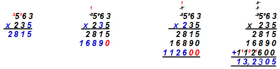
Long multiplication calculations – Times tables are not readily
available for multipliers of over twelve, so greater calculations are done in
steps. The first Step is to multiply the units, then the tens and then
hundreds. Finally all the answer lines are added. Remember to add a zero (0) as
will be required for the ten line to be the correct value, as in Example 18 below:
|
|
|
|
|
|
Example : |
|||
|
Step 1 |
Step 2 |
Step 3 |
Step 4 |
|
|
|
|
|
|
H T
U |
H T U |
H T U |
H
T U |
|
|
|||

|
|
|
|
|
|
|||||||||
|
Example : |
|
||||||||||||
|
Step 1 |
Step 2 |
Step 3 |
Step 4 |
|
|||||||||
|
|
|
|
|
|
|||||||||
|
H
T U |
H T U |
H T U |
T
H T U |
|
|||||||||
|
|
|
||||||||||||
|
|
||||||||||||
|
Check your progress multiplication -try these calculations: |
|
|
|||||||||||
|
|
|
|
|||||||||||
|
Question 1: |
|
Question 2: |
|
Question 3: |
|
Question 4: |
|
|
|||||
|
|
|
|
|
|
|||||||||
|
4 2 3 |
2 3 7 |
5 6 8 |
7 7 7 |
|
|||||||||
|
x 2 5 |
x 5 2 |
x
3 1 2 |
x 4
3 6 |
|
|||||||||
|
? ? ? |
? ? ?
|
? ? ?
|
? ? ?
|
|
|||||||||
|
|
|
|
|
|
|||||||||
|
|
|
|
|
|
|||||||||
|
Answers multiplication - as below: |
|
|
|||||||||||
|
|
|
|
|||||||||||
|
Answer 1: |
|
Answer 2: |
|
Answer 3: |
|
Answer 4: |
|
|
|||||
|
|
|
|
|
|
|||||||||
|
4
2 3 |
2
3 7 |
5 6 8 |
7 7 7 |
|
|||||||||
|
x 2 5 |
x 5 2 |
x
3 1 2 |
x
4 3 6 |
|
|||||||||
|
2 1
1 5 |
4
7 4
|
1 1 3 6 |
4 6 6 2 |
|
|||||||||
|
8
4 6 0 |
1 1 8 5 0 |
5 6 8 0 |
2 3 3 1 0 |
|
|||||||||
|
1 0,5 7 5 |
1 2,3 2 4 |
1 7 0 4 0 0 |
3 1 0 8 0 0 |
|
|||||||||
|
|
|
1 7 7,2 1 6 |
3 3 8 7 7 2 |
|
|||||||||
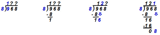
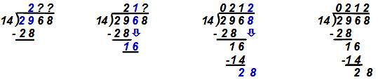
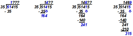
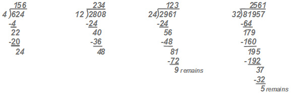
Long division calculations – In example 20 below, Step 1
estimates how many divisors (5) fit in the
left hand boxed numeral (1). If it will not
fit, Step 2 estimates how many fit into the first + the second numerals (1 & 3), in
the example giving 2. As 2 x 5 =10 we subtract 10 from 1
& 3 to leave 3. Step 3 drops the third numeral (5) to give 35. Step
4 finds that the divisor fits 7 times into 35
giving a final answer of 27.
|
Example : |
|||
|
Step 1 |
Step 2 |
Step 3 |
Step 4 |
|
|
|||

|
Example : |
|||
|
Step 1 |
Step 2 |
Step 3 |
Step 4 |
|
|
|||
|
Example : |
|||
|
Step 1 |
Step 2 |
Step 3 |
Step 4 |
|
|
|||
|
Example : |
|||
|
Step 1 |
Step 2 |
Step 3 |
Step 4 |
|
|
|||
|
Example : |
|||
|
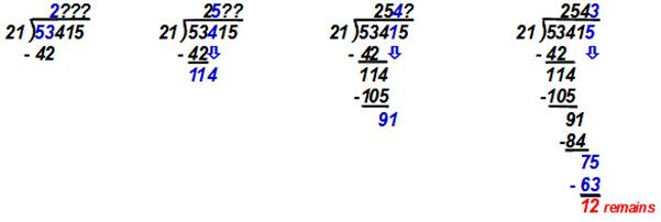
If the quantity does not share equally we write down a
remainder (in red below), or write it as a
fraction (see next Section 2.3) |
|||
|
Step 1 |
Step 2 |
Step 3 |
Step 4 |
|
|
|||
|
Check your progress long division -try these calculations: |
|
|||||||
|
|
|
|||||||
|
Question 1: |
|
Question 2: |
|
Question 3: |
|
Question 4: |
|
|
|
|
||||||||
|
|
|
|||||||
|
|
||||||||
|
|
||||||||
|
Answers long division - as below: |
|
|||||||
|
|
|
|||||||
|
Answer 1: |
|
Answer 2: |
|
Answer 3: |
|
Answer 4: |
|
|
|
|
||||||||
|
|
||||||||

2.3 Fractions and decimals
Fractions
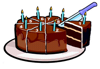
To share a cake we slice it into parts. Each part can be called a fraction of the whole cake, for example, slice number 1 below is from a cake with 8 slices. It is one eighth of the cake. All fractions are parts of a whole.
|
Fraction’s are expressed
(written) separated by a line – as above |
1 |
of a cake. |
|
8 |
A numerator - a number on top showing us the parts of the whole we have.
A denominator - a bottom number showing how many parts make up the whole.
The cake could have been cut into any other fractions, such as:
|
1 |
= |
one slice of a whole cake cut into two |
= |
half a cake |
|
2 |
||||
|
|
|
|
|
|
|
1 |
= |
one slice of a whole cake cut into four |
= |
quarter of a cake |
|
4 |
||||
|
|
|
|
|
|
|
1 |
= |
one slice of a whole cake cut into ten |
= |
tenth of a cake |
|
10 |
Calculating with fractions
Addition – with a common denominator
To add fractions the denominators (the number below the line) must be the same (called common). The answer is found by totalling the numerators (number above the line) of each fraction and expressing with the common denominator, as below:
|
1 |
+ |
2 |
+ |
3 |
+ |
4 |
= |
10 |
half a |
||||
|
20 |
|
20 |
|
20 |
|
20 |
|
20 |
cake |
||||
|
Expression and Substitution However, we could have received several cake slices expressed as fractions below: |
|||||||||||||
|
4 |
= |
four slices of a whole cake cut into eight |
= |
1 |
half of cake |
||||||||
|
8 |
2 |
||||||||||||
|
|
|
|
|
|
|||||||||
|
4 |
= |
four slices of a whole cake cut into twelve |
= |
1 |
third of cake |
||||||||
|
12 |
3 |
||||||||||||
You will notice that both 4 slices of an 8 slice cake and10 slices of a 20 slice cake both are half of each cake. So fractions can be expressed with differing numerator and denominator and still be the same value as a part of the whole, for instance:
|
10 |
= |
1 |
= |
5 |
= |
2 |
= |
10 |
|
|
20 |
|
2 |
|
10 |
|
4 |
|
20 |
|
The rule is that we must change both the top and the bottom line of a fraction with the same factor (divisor or multiplier) if the fraction is to retain its value. Applying this rule is called substitution.
|
10 x 4 |
= |
40
÷ 10 |
= |
4 x 3 |
= |
12
÷ 12 |
= |
1 |
ü |
|
20
x 4 |
|
80 ÷ 10 |
|
8 x 3 |
|
24
÷ 12 |
|
2 |
|
|
|
|
|
|
|
|
|
|
|
|
|
Note below that substitution does not work by adding or subtracting to numerator and denominator. Only by multiplying and dividing equally gives a correct answer. |
|||||||||
|
|
|
|
|
|
|
|
|
|
|
|
10 + 4 |
= |
14 |
|
X Wrong!! |
|
10 - 4 |
=
|
6 |
X Wrong
!! |
|
20
+ 4 |
|
24 |
|
|
20
- 4 |
|
16 |
||
|
|
|
|
|
|
|
|
|
|
|
Addition – fractions without a common
denominator
We need a common denominator to add fractions. But in the example below different cakes have been cut into different numbers of slices. Each cake’s denominator is different. We have to change each fraction to the same denominator but still express its same value (part of a whole cake). All fractions must be of same sized slices.
To find our common denominator we could multiply all denominators, as below:
|
10 |
+ |
3 |
+ |
6 |
+ |
2 |
= |
? |
|
|
20 |
|
5 |
|
10 |
|
4 |
|
? |
|
|
|
|
|
|
|
|
|
|
|
|
|
20 |
x |
5 |
x |
10 |
x |
4 |
= |
4000 |
|
The common denominator in this case is 4000, a very large number of tiny slices of a cake and a complex number for calculations. It will be easier for us to find the lowest common denominator, the smallest number that all denominators will divide into without leaving any remainder. In the example below it is 20.
Step 1 - draw a long line above our chosen lowest common denominator 20.
Step 2 - divide the lowest common denominator with each fraction’s denominator.
Step 3 - multiply the answer with each old numerator. Mathematical balance is regained with the value being equal to each old fraction’s value. Finally total the numerators and express the answer with the lowest common denominator.
|
10 |
+ |
4 |
+ |
6 |
+ |
2 |
= |
? |
|
|
|
|
||||||
|
20 |
5 |
10 |
4 |
? |
|
|
|
|
||||||||||
|
|
|
|
|
|
|
|
|
|
|
|
|
|
||||||
|
Step 3: |
|
|
|
|
|
|
|
|
|
|
|
|
||||||
|
1 x 10 = 20 |
|
4 x 4 =
12 |
|
2
x 6 = 12 |
|
5 x 2 = 10 |
|
|
|
|
|
|
||||||
|
|
|
|
|
|
|
|
|
|
|
|
|
|
||||||
|
Step 2: |
|
|
|
|
|
|
|
|
|
|
|
|
||||||
|
20 ÷ 20 =
1 |
|
20 ÷ 5 =
4 |
|
20 ÷ 10
= 2 |
|
20 ÷ 4
= 5 |
|
|
|
|
|
|
||||||
|
|
|
|
|
|
|
|
|
|
|
|
|
|
||||||
|
Step 1: |
|
|
|
|
|
|
|
|
|
|
|
|
|
|||||
|
10 +
16 + 12
+ 10 |
= |
48
|
= |
2 |
8 |
= |
2 |
2 |
||||||||||
|
20 |
20 |
20 |
5 |
|||||||||||||||
|
|
|
|
|
|
|
|
|
|
|
|
|
|
|
|||||
Unlike earlier examples our answer is an improper fraction. The numerator 48 is greater than the denominator 20. Remember, the slices are from more than one cake. To express properly we divide the numerator with the denominator. The 48 pieces from 20 sliced cakes could be reassembled as 2 wholes with 8 slices left over. Eight twentieths can be substituted as the same as two fifths of a cake.
Sometimes we have to add whole numbers with fractions as below. The method is to convert each whole number with fraction into an improper fraction, find the common denominator and then continue as normal addition. The answer, an improper fraction, is converted back to whole number with any remainder fraction. The remainder can be substituted with lowest denominator for the simplest expression.
|
1 |
1 |
|
+ |
2 |
2 |
|
+ |
1 |
1 |
|
= |
? |
|
|
|
|
|
|
|
2 |
|
3 |
|
6 |
|
|
|
|
|
|
|
|||||||
|
|
|
|
|
|
|
|
|
|
|
|
|
|
|
|
|
|
|
|
|
2 |
+ |
1 |
+ |
6 |
+ |
2 |
+ |
6 |
+ |
1 |
= |
? |
|
|
|
|
|
|
|
2 |
|
2 |
3 |
|
3 |
6 |
|
6 |
|
|
|
|
|
|
||||
|
|
|
|
|
|
|
|
|
|
|
|
|
|
|
|
|
|
|
|
|
|
3 |
|
+ |
|
8 |
|
+ |
|
7 |
|
= |
? |
|
|
|
|
|
|
|
|
2 |
|
|
3 |
|
|
6 |
|
|
|
|
|
|
|
||||
|
|
|
|
|
|
|
|
|
|
|
|
|
|
|
|
|
|
|
|
|
|
9
+ 16 + 7 |
|
= |
32 |
= |
5 |
2 |
= |
5 |
1 |
||||||||
|
|
|
6 |
|
|
|
|
6 |
6 |
3 |
|||||||||
Subtraction
As with adding, subtracting fractions requires a common denominator. The answer is found by subtracting the numerators and expressing with the common denominator:
|
19 |
- |
10 |
- |
5 |
- |
3 |
= |
1 |
|
20 |
|
20 |
|
20 |
|
20 |
|
20 |
If the denominator is not common, we have to substitute to express all with the same denominator.
Step 1 - draw a long line above our chosen lowest common denominator 20.
Step 2 - divide the lowest common denominator with each fraction’s denominator.
Step 3 - multiply the answer with each old numerator. Mathematical balance is regained with the value being equal to each old fraction’s value. Finally subtract the numerators and express the answer with the lowest common denominator.
|
19 |
- |
1 |
- |
2 |
- |
1 |
= |
? |
|
|
|
|
|
|
|
20 |
2 |
10 |
5 |
? |
|
|
|
|
|
|||||
|
|
|
|
|
|
|
|
|
|
|
|
|
|
|
|
|
Step 3: |
|
|
|
|
|
|
|
|
|
|
|
|
|
|
|
1 x 19 = 19 |
|
10 x 1
= 10 |
|
2
x 2 = 4 |
|
4 x 1 = 4 |
|
|
|
|
|
|
|
|
|
|
|
|
|
|
|
|
|
|
|
|
|
|
|
|
|
Step 2: |
|
|
|
|
|
|
|
|
|
|
|
|
|
|
|
20 ÷ 20 =
1 |
|
20 ÷ 2 =
10 |
|
20 ÷ 10
= 2 |
|
20 ÷ 4
= 5 |
|
|
|
|
|
|
|
|
|
|
|
|
|
|
|
|
|
|
|
|
|
|
|
|
|
Step 1: |
|
|
|
|
|
|
|
|
|
|
|
|
|
|
|
19 -
10 - 4
- 4 |
= |
1 |
|
|
|
|
|
|
||||||
|
20 |
20 |
|
|
|||||||||||
Sometimes we have to subtract whole numbers with fractions. The method is to convert each number with fraction into an improper fraction, find the common denominator and then continue as normal subtraction. The answer, an improper fraction, is converted back to whole number with any remainder. The remainder can be substituted with lowest denominator for the simplest expression.
|
5 |
1 |
|
- |
1 |
2 |
|
- |
2 |
3 |
|
= |
? |
|
|
|
|
|
|
|
2 |
|
3 |
|
6 |
|
|
|
|
|
|
|
|||||||
|
|
|
|
|
|
|
|
|
|
|
|
|
|
|
|
|
|
|
|
|
10 |
+ |
1 |
- |
3 |
+ |
2 |
- |
12 |
+ |
3 |
= |
? |
|
|
|
|
|
|
|
2 |
|
2 |
3 |
|
3 |
6 |
|
6 |
|
|
|
|
|
|
||||
|
|
|
|
|
|
|
|
|
|
|
|
|
|
|
|
|
|
|
|
|
|
11 |
|
- |
|
5 |
|
- |
|
15 |
|
= |
? |
|
|
|
|
|
|
|
|
2 |
|
|
3 |
|
|
6 |
|
|
|
|
|
|
|
||||
|
|
|
|
|
|
|
|
|
|
|
|
|
|
|
|
|
|
|
|
|
|
33 -
10 - 15 |
|
= |
8 |
= |
1 |
2 |
= |
1 |
1 |
||||||||
|
|
|
|
6 |
|
|
|
|
6 |
6 |
3 |
||||||||
Check your progress
adding and subtracting fractions -try these
calculations:
|
Question 1: |
|
Question 2: |
|
||||||||||||||||||||||||||||||||||||
|
1 |
+ |
2 |
+ |
1 |
= |
? |
|
2 |
+ |
3 |
+ |
4 |
= |
? |
|
||||||||||||||||||||||||
|
6 |
6 |
6 |
? |
|
10 |
10 |
10 |
? |
|
||||||||||||||||||||||||||||||
|
|
|||||||||||||||||||||||||||||||||||||||
|
Question 3: |
|
||||||||||||||||||||||||||||||||||||||
|
1 |
+ |
2 |
+ |
5 |
= |
? |
|
||||||||||||||||||||||||||||||||
|
2 |
3 |
6 |
? |
|
|||||||||||||||||||||||||||||||||||
|
|
|||||||||||||||||||||||||||||||||||||||
|
Question 4: |
|
Question 5: |
|
||||||||||||||||||||||||||||||||||||
|
9 |
- |
2 |
- |
5 |
= |
? |
|
19 |
- |
4 |
- |
4 |
= |
? |
|
||||||||||||||||||||||||
|
10 |
10 |
10 |
? |
|
22 |
22 |
22 |
? |
|
||||||||||||||||||||||||||||||
|
|
|||||||||||||||||||||||||||||||||||||||
|
Question 6: |
|
||||||||||||||||||||||||||||||||||||||
|
9 |
- |
1 |
- |
2 |
= |
? |
|
||||||||||||||||||||||||||||||||
|
12 |
3 |
6 |
? |
|
|||||||||||||||||||||||||||||||||||
|
|
|||||||||||||||||||||||||||||||||||||||
|
Question 7: |
|
||||||||||||||||||||||||||||||||||||||
|
1 |
1 |
+ |
3 |
3 |
+ |
2 |
3 |
= |
? |
|
|||||||||||||||||||||||||||||
|
2 |
4 |
8 |
? |
|
|||||||||||||||||||||||||||||||||||
|
|
|||||||||||||||||||||||||||||||||||||||
|
Question 8: |
|||||||||||||||||||||||||||||||||||||||
|
8 |
2 |
- |
2 |
1 |
- |
3 |
4 |
= |
? |
|
|||||||||||||||||||||||||||||
|
3 |
2 |
6 |
? |
|
|||||||||||||||||||||||||||||||||||
|
|
|
||||||||||||||||||||||||||||||||||||||
|
Answers adding and subtracting fractions - as below: |
|||||||||||||||||||||||||||||||||||||||
|
|
|||||||||||||||||||||||||||||||||||||||
|
Answer 1: |
|
Answer 2: |
|
||||||||||||||||||||||||||||||||||||
|
1 |
+ |
2 |
+ |
1 |
= |
4 |
|
2 |
+ |
3 |
+ |
4 |
= |
9 |
|
||||||||||||||||||||||||
|
6 |
6 |
6 |
6 |
|
10 |
10 |
10 |
10 |
|
||||||||||||||||||||||||||||||
|
|
|
||||||||||||||||||||||||||||||||||||||
|
Answer 3: |
|
||||||||||||||||||||||||||||||||||||||
|
1 |
+ |
2 |
+ |
5 |
= |
3 +
4 + 5
|
= |
12 |
= |
2 |
|
||||||||||||||||||||||||||||
|
2 |
3 |
6 |
6 |
6 |
|
||||||||||||||||||||||||||||||||||
|
|
|
||||||||||||||||||||||||||||||||||||||
|
Answer 4: |
|
Answer 5: |
|
||||||||||||||||||||||||||||||||||||
|
9 |
- |
2 |
- |
5 |
= |
2 |
|
19 |
- |
4 |
- |
4 |
= |
11 |
= |
1 |
|
||||||||||||||||||||||
|
10 |
10 |
10 |
10 |
|
22 |
22 |
22 |
22 |
2 |
|
|||||||||||||||||||||||||||||
|
|
|
||||||||||||||||||||||||||||||||||||||
|
Answer 6: |
|
||||||||||||||||||||||||||||||||||||||
|
9 |
- |
1 |
- |
2 |
= |
9 - 4 - 4 |
= |
1 |
|
||||||||||||||||||||||||||||||
|
12 |
3 |
6 |
12 |
12 |
|
||||||||||||||||||||||||||||||||||
|
|
|||||||||||||||||||||||||||||||||||||||
|
Answer 7: |
|||||||||||||||||||||||||||||||||||||||
|
1 |
1 |
+ |
3 |
3 |
+ |
2 |
3 |
= |
3 |
+ |
15 |
+ |
19 |
= |
12 + 30 + 19 |
= |
61 |
= |
7 |
5 |
|||||||||||||||||||
|
2 |
4 |
8 |
2 |
4 |
8 |
8 |
8 |
8 |
|||||||||||||||||||||||||||||||
|
|
|||||||||||||||||||||||||||||||||||||||
|
Answer 8: |
|||||||||||||||||||||||||||||||||||||||
|
8 |
2 |
- |
2 |
1 |
- |
3 |
4 |
= |
26 |
- |
5 |
- |
22 |
= |
52 - 15 - 22 |
= |
15 |
= |
2 |
3 |
|||||||||||||||||||
|
3 |
2 |
6 |
3 |
2 |
6 |
6 |
6 |
6 |
|||||||||||||||||||||||||||||||
Multiplication
with fractions
Common
denominators are not required to multiply fractions, as shown below:
|
Example : |
|
Example : |
|
|
||||||||||||||||||||||||||||
|
1 |
x |
1 |
= |
1 |
|
1 |
x |
2 |
x |
4 |
= |
8 |
= |
2 |
|
|
||||||||||||||||
|
2 |
2 |
4 |
|
2 |
3 |
6 |
36 |
9 |
|
|
||||||||||||||||||||||
|
With whole
number and fraction combinations, each can be multiplied separately. Note
that the answer is usually expressed as the simplest fraction (substituted
with a lowest common denominator). In 8 over 36 above, both are divided by 4. |
||||||||||||||||||||||||||||||||
|
Example : |
|
Example : |
||||||||||||||||||||||||||||||
|
2 |
1 |
x |
3 |
3 |
= |
6 |
3 |
|
3 |
2 |
x |
4 |
4 |
x |
6 |
1 |
= |
72 |
8 |
= |
72 |
1 |
||||||||||
|
2 |
4 |
8 |
|
3 |
6 |
4 |
72 |
9 |
||||||||||||||||||||||||
|
Check your progress multiplying fractions -try these calculations: |
||||||||||||||||||||||||||||||||
|
Question 1: |
|
Question 2: |
|
|
||||||||||||||||||||||||||||
|
3 |
x |
2 |
= |
? |
|
1 |
x |
5 |
x |
2 |
= |
? |
|
|
|
|
||||||||||||||||
|
5 |
3 |
|
2 |
6 |
3 |
|
|
|
||||||||||||||||||||||||
|
|
||||||||||||||||||||||||||||||||
|
Question 3: |
|
Question 4: |
|
|||||||||||||||||||||||||||||
|
2 |
5 |
x |
2 |
|
? |
|
|
5 |
2 |
x |
4 |
5 |
x |
3 |
1 |
= |
? |
|
|
|
|
|||||||||||
|
6 |
|
|
3 |
6 |
5 |
|
|
|||||||||||||||||||||||||
|
Answers multiplying fractions -
as below: |
||||||||||||||||||||||||||||||||
|
Answer 1: |
|
Answer 2: |
|
|
||||||||||||||||||||||||||||
|
3 |
x |
2 |
= |
6 |
|
1 |
x |
5 |
x |
2
|
= |
10 |
= |
5 |
|
|
||||||||||||||||
|
5 |
3 |
15 |
|
2 |
6 |
3 |
36 |
18 |
|
|
||||||||||||||||||||||
|
|
||||||||||||||||||||||||||||||||
|
Answer 3: |
|
Answer
4: |
||||||||||||||||||||||||||||||
|
2 |
5 |
x |
2 |
3 |
= |
4 |
15 |
|
5 |
2 |
x |
4 |
5 |
x |
3 |
1 |
= |
60 |
10 |
= |
60 |
1 |
||||||||||
|
6 |
4 |
24 |
|
3 |
6 |
5 |
90 |
9 |
||||||||||||||||||||||||
Division
with fractions
Dividing fractions with fractions is easiest achieved by inverting the second fraction’s numerator and denominator and then multiplying. Note that the answer is usually expressed by substitution as the simplest fraction.
|
NUM |
÷ |
num |
= |
NUM |
x |
den |
= |
Nd |
||||||
|
DEN |
den |
DEN |
num |
Dn |
||||||||||
|
|
||||||||||||||
|
Example : |
||||||||||||||
|
3 |
÷ |
1 |
= |
3 |
x |
2 |
= |
6 |
= |
1 |
2 |
= |
1 |
1 |
|
4 |
2 |
4 |
1 |
4 |
4 |
2 |
||||||||
|
Example : |
||||||||||||||
|
6 |
÷ |
1 |
= |
6 |
x |
3 |
= |
18 |
= |
2 |
2 |
= |
2 |
1 |
|
8 |
3 |
8 |
1 |
8 |
8 |
4 |
||||||||
With whole number and fraction combinations
it is easiest to covert each to an improper fraction. Then invert the dividing
fraction and multiplying with it. Note that the answer is usually expressed as
the simplest.
|
Example : |
|
||||||||||||||||||||||||||||||
|
1 |
1 |
÷ |
|
1 |
= |
2 + 1 |
÷ |
1 |
= |
3 |
÷ |
1 |
= |
3 |
x |
4 |
= |
12 |
= |
6 |
|
||||||||||
|
2 |
4 |
2 |
4 |
2 |
4 |
2 |
1 |
2 |
|
||||||||||||||||||||||
|
|
|||||||||||||||||||||||||||||||
|
Example : |
|||||||||||||||||||||||||||||||
|
2 |
1 |
÷ |
1 |
2 |
= |
6 + 1 |
÷ |
6 + 2 |
= |
7 |
÷ |
8 |
= |
7 |
x |
6 |
= |
42 |
= |
1 |
18 |
||||||||||
|
3 |
6 |
3 |
6 |
3 |
6 |
3 |
8 |
24 |
24 |
||||||||||||||||||||||
|
|
|||||||||||||||||||||||||||||||
|
Check your progress dividing
fractions -try
these calculations: |
|||||||||||||||||||||||||||||||
|
Question 1: |
|
||||||||||||||||||||||||||||||
|
1 |
÷ |
1 |
= |
? |
|
|
|
|
|
|
|
|
|
|
|||||||||||||||||
|
2
|
4 |
|
|
|
|
||||||||||||||||||||||||||
|
|
|||||||||||||||||||||||||||||||
|
Question 2: |
|
||||||||||||||||||||||||||||||
|
5 |
÷ |
2 |
= |
? |
|
|
|
|
|
|
|
|
|
|
|||||||||||||||||
|
6
|
3 |
|
|
|
|
||||||||||||||||||||||||||
|
|
|
|
|
|
|
|
|
|
|
|
|
|
|
||||||||||||||||||
|
Question 3: |
|
|
|||||||||||||||||||||||||||||
|
2 |
1 |
÷ |
1 |
1 |
|
= |
|
? |
|
|
|
|
|
|
|
|
|
|
|
|
|
||||||||||
|
2 |
4 |
|
|
|
|
|
|
||||||||||||||||||||||||
|
|
|||||||||||||||||||||||||||||||
|
Question 4: |
|
||||||||||||||||||||||||||||||
|
2 |
5 |
÷ |
1 |
6 |
|
= |
|
? |
|
|
|
|
|
|
|
|
|
|
|
|
|
||||||||||
|
6 |
9 |
|
|
|
|
|
|
||||||||||||||||||||||||
|
|
|||||||||||||||||||||||||||||||
|
Answers dividing fractions - as below: |
|||||||||||||||||||||||||||||||
|
Answer 1: |
|||||||||||||||||||||||||||||||
|
1 |
÷ |
1 |
= |
1 |
x |
4 |
= |
4 |
= |
2 |
|
|
|
|
|||||||||||||||||
|
2 |
4 |
2 |
1 |
2 |
|
|
|||||||||||||||||||||||||
|
|
|||||||||||||||||||||||||||||||
|
Answer 2: |
|||||||||||||||||||||||||||||||
|
5 |
÷ |
2 |
= |
5 |
x |
3 |
= |
15 |
= |
1 |
3 |
= |
1 |
1 |
|||||||||||||||||
|
6 |
3 |
6 |
2 |
12 |
12 |
4 |
|||||||||||||||||||||||||
|
|
|
|
|
|
|
|
|
|
|
|
|
|
|
|
|||||||||||||||||
|
Answer 3: |
|
||||||||||||||||||||||||||||||
|
2 |
1 |
÷ |
1 |
1 |
= |
4
+ 1 |
÷ |
4
+ 1 |
= |
5 |
÷ |
5 |
= |
5 |
x |
4 |
= |
20 |
= |
2 |
|
||||||||||
|
2 |
4 |
2 |
4 |
2 |
4 |
2 |
5 |
10 |
|
||||||||||||||||||||||
|
|
|||||||||||||||||||||||||||||||
|
Answer 4: |
|||||||||||||||||||||||||||||||
|
2 |
5 |
÷ |
1 |
6 |
= |
12 +
5 |
÷ |
9
+ 6 |
= |
17 |
÷ |
15 |
= |
17 |
x |
9 |
= |
153 |
= |
1 |
21 |
||||||||||
|
6 |
9 |
6 |
9 |
6 |
9 |
6 |
15 |
90 |
30 |
||||||||||||||||||||||
Decimals
A dot or point (·) following a numeral is another way to express a fraction of its whole. A decimal point expresses a fraction that is a division of ten or its multiples when using the base ten numbering system (see more about base in Section 1.3), for instance:
1· 0 One whole only.
1· 1
One whole and one tenth of a whole.
1· 25
One whole and twenty five hundredths whole (¼).
1· 5
One whole and five tenths whole
(½).
1· 75
One whole and seventy five hundredths whole (¾).
1· 9
One whole and nine tenths of a whole.
The decimal place determines the fractions multiple of ten. If it is placed immediately to the right of a whole number it expresses a tenth (1 x 10), if it is placed two spaces to the right it expresses one hundredth (10 x 10), etc, as below:
1· 1
One whole and one tenth of a whole.
1·
01 One whole and one hundredth of a
whole.
1·
001 One whole and one thousandths of a
whole.
1·
0001 One whole and the thousandths of a whole.
1·
00001 One whole and one hundred thousandths of a
whole.
1·
000001 One whole and one millionths of a whole.
Adding
and subtracting
Writing sums in a table format (or columns) ensures that the decimal place of the answer is correctly positioned above the decimal place of the question.
|
Example: |
|
Example: |
|
Example: |
|
|
1· 1 |
1· 52 |
106· 325 |
|||
|
+ 3· 6 |
+ 33· 34 |
+ 521· 520 |
|||
|
4· 7 |
34· 86 |
627· 845 |
|||
|
|
|
|
|||
|
|
|
|
|||
|
Example: |
|
Example: |
|
Example: |
|
|
3· 6 |
33· 34 |
521· 520 |
|||
|
- 1· 1 |
- 1· 52 |
- 106· 325 |
|||
|
2· 5 |
31· 82 |
415· 195 |
|||
Multiplying
It is easiest to multiply each whole numeral and decimal numeral as in long multiplication. After completing the calculation, the answer’s decimal place is determined from counting the places found in the question, as below:
|
Example: |
|
Example: |
|
Example: |
|
|
3·6 |
3 3·3 4 |
2 1·5 1 1 |
|||
|
x 1·1 |
x 2·1 2 |
x 6·3 2 5 |
|||
|
3 6 |
6 6 6 8 |
1 0 7 5 5 5 |
|||
|
3
6 0 |
3 3 3 4 0 |
4 3 0 2 2 0 |
|||
|
3·9 6 |
6
6 6 8 0 0 |
6 4 5 3 3 0 0 |
|||
|
|
7
0·6 8 0 8 |
1 2 9 0 6 6 0
0 0 |
|||
|
|
|
1 3 6·0 5 7 0 7 5 |
|||
As a double check, ensure that the answer’s decimal place roughly meets the expected units. Above 3 x 1 should roughly be 3 units and 33 x 2 should be 66.
Dividing
It is easiest to multiply each numeral and decimal by a multiple of ten until they become whole numbers, before calculating as in long division. If both the divisor and the divider are multiplied by the same amount then the proportions and answer will be correct.
|
Example: |
|
Example: |
|
|
|
(2 4
÷ 0·2) x 1 0 = (2 4 0 ÷
2) = |
(3 6 ÷ 0·0 6) x 1 0 0 = (3 6 0 0 ÷ 6) = |
|||
|
|
|
|||
|
1 2
0 |
6 0
0 |
|||
|
2 )2 4 0 |
6 )3 6 0 0 |
|||
|
|
|
|||
|
Example: |
|
Example: |
|
|
|
4·8 ÷ 2 x 1 0 = (4
8 ÷
2 0) = |
(1 5·7 5 ÷ 0·75) x 1 0 0 = (1 5
7 5 ÷ 75) = |
|||
|
|
|
|||
|
2·4 |
2 1 |
|||
|
2 0 )4 8·0 |
75
)1 5 7 5 |
|||
|
4
0 |
1 5 0 |
|||
|
8
0
|
7 5 |
|||
In the examples above the numerals and decimals were multiplied to become whole numbers, but we could just have easily moved the decimal places to the right to achieve the same result.
Converting fractions to
decimals
To convert fractions to decimals the numerator is divided by the denominator. Don’t
always expect a simple decimal answer unless the fraction is a division of ten.
|
Example: |
|
Example: |
|
Example: |
||||||
|
1 |
= |
0·5 |
|
3 |
= |
0·7 5 |
|
5 |
= |
0· 6 2 5 |
|
2 |
2)1·0 |
|
4 |
4)3·0 0 |
|
8 |
8)5·0 0 0 |
|||
|
|
|
|
|
|
|
2
8 |
|
|
|
4
8 |
|
|
|
|
|
|
|
2 0 |
|
|
|
2 0 |
|
|
|
|
|
|
|
|
|
|
|
1 6 |
|
|
|
|
|
|
|
|
|
|
|
4 0 |
Check your progress decimals -try these
calculations: |
|||||||
|
Question 1: |
|
Question 2: |
|
Question 3: |
|
||
|
5· 2 |
11· 23 |
345· 345 |
|||||
|
+ 3· 6 |
+ 24· 62 |
+ 123· 123 |
|||||
|
? |
? |
? |
|||||
|
|
|
|
|||||
|
Question 4: |
|
Question 5: |
|
Question 6: |
|
||
|
5· 2 |
24· 62 |
573· 267 |
|||||
|
- 3· 6 |
- 1· 52 |
- 106·
325 |
|||||
|
? |
? |
? |
|||||
|
|
|
|
|||||
|
Question 7: |
|
Question 8: |
|
Question 9: |
|
||
|
5·7 |
2
7·3 2 |
4 1·2 2 |
|||||
|
x 2·1 |
x 1·4 2 |
x 2·3 3 |
|||||
|
? |
? |
? |
|||||
|
|
|
|
|||||
|
Question 10: |
|
Question 11: |
|
|
|||
|
7·2 ÷ 4 =
? |
3 4·2 5 ÷ 0·25 =
? |
|
|||||
|
Answers decimals - as below: |
|||||
|
Answer 1: |
|
Answer 2: |
|
Answer 3: |
|
|
5· 2 |
11· 23 |
345· 345 |
|||
|
+ 3· 6 |
+ 24· 62 |
+ 123· 123 |
|||
|
8· 8 |
35· 85 |
468· 468 |
|||
|
|
|
|
|||
|
Answer 4: |
|
Answer 5: |
|
Answer 6: |
|
|
5· 2 |
24· 62 |
573· 267 |
|||
|
- 3· 6 |
- 1· 52 |
- 106· 325 |
|||
|
1· 6 |
23· 10 |
466· 942 |
|||
|
Answer
7: |
|
Answer
8: |
|
Answer
9: |
|
|||
|
5·7 |
2 7·3 2 |
4 1·2 2 |
||||||
|
x 2·1 |
x 1·4 2 |
x 2·3 3 |
||||||
|
5 7 |
5 4 6 4 |
1 2 3 6 6 |
||||||
|
1
1 4 0 |
1 0 9
2 8 0 |
1 2 3 6 6 0 |
||||||
|
1
1·9 7 |
2
7 3 2 0 0 |
8 2 4 4 0 0 |
||||||
|
|
3
8·7 9 4 4 |
9 6·0 4 2 6 |
||||||
|
|
|
|
||||||
|
Answer 10: |
|
Answer 11: |
|
|||||
|
(7·2 ÷ 4) x 1 0 =
72 ÷ 4 0 = |
(3 4·2 5 ÷ 0·25) x 1 0
0 = 3 4 2 5 ÷ 25 = |
|||||||
|
|
|
|||||||
|
1·8 |
1 3 7 |
|||||||
|
4 0 )72·0 |
25 )3 4 2 5 |
|||||||
|
4
0 |
2 5 |
|||||||
|
3 2
0
|
9 2 5 |
|||||||
2.3
Calculating machines
The abacus – a counting machine
The abacus is an ancient counting machine that is constructed in a variety of ways across the world. It consists of a frame supporting a number of rails upon which beads can slide, so recording counting operations (addition or subtraction). Each rail supports a group of beads that are attributed with levels of value.
In the decimal based Abacus shown below, the beads on the bottom rail each have a value of one unit, the rail above contains beads of value ten, the rail above contains beads of value one hundred and the rail above contains beads of value one thousand.

When the maximum number of beads for each rail is slid to the left, their combined value will equal one of that above. The operation is to slide one of the above to the left and slide the ten below back to the right. The status shown on the abacus is the value of one thousand, four hundreds, two tens and three units (1423 units in base ten system). This Abacus is limited to recording a maximum value of 10,999 units.
The calculator
Addition, subtraction, multiplication and division of fractions and decimals, as well as conversions from fraction form to decimal form, can all be undertaken on a standard calculator. A scientific calculator has additional functions including but not limited to exponents, roots, constants and trigonometry.
The keypads and operation can differ from one calculator to another, as described in the user’s manuals, but the keying below is common. If in doubt, as with algebra, use the processing order of bemdas.
Addition and subtraction
Press all addition values, equal, press all negative values, equal. Example:
|
2 |
+ |
3 |
+ |
4 |
+ |
5 |
+ |
6 |
= |
20 |
- |
6 |
- |
5 |
- |
4 |
- |
3 |
- |
2 |
= |
0 |
Multiplication and division
Press all multiplication values, equal, press all divisions (÷ key is / ), equal. Example:
|
2 |
x |
3 |
x |
4 |
x |
5 |
x |
6 |
= |
720 |
/ |
6 |
/ |
5 |
/ |
4 |
/ |
3 |
/ |
2 |
= |
0 |
Mixed operators
The problem below is set out in the bemdas sequence. Example,
2 x 3
x 4 = 24 ÷ 2 ÷ 3 = 4 + 2 + 3 = 9 -
4 - 3 = 2
The problem is set out using brackets to clarify the bemdas sequence. Example:
|
( |
2 |
x |
3 |
x |
4 |
) |
= |
24 |
( |
/ |
2 |
/ |
3 |
) |
= |
4 |
( |
+ |
2 |
+ |
3 |
) |
= |
9 |
( |
- |
4 |
- |
3 |
) |
= |
2 |
Fractions
Standard calculators may not have a dedicated fractions keypad. Each fraction must be resolved (as if a division in brackets) into a decimal fraction. Only then can the decimal fractions be re-entered for the division operation. Example:
|
1 |
÷ |
1 |
= |
|
||||||||||||||||||||||||
|
2 |
4 |
|
||||||||||||||||||||||||||
|
|
|
|
|
|
|
|||||||||||||||||||||||
|
( |
1 |
/ |
2 |
) |
= |
·5 |
|
|
( |
1 |
/ |
4 |
) |
= |
·25 |
|
·5 |
/ |
·25 |
= |
2 |
|||||||
If a MS (memory store) and a MR (memory recall) are available in your calculator, then rearranging the processing order can simplify keying entries, as below.
|
1 |
/ |
4 |
= |
·25 |
MS |
1 |
/ |
2 |
= |
·5 |
/ |
MR |
= |
2 |
Some scientific calculators may have a fraction keypad to press between numerator and denominator entries to enable fractional to be calculated directly. Example:
|
2 |
- |
( |
4 |
x |
1 |
) |
= |
|
3 |
6 |
2 |
|
2 |
a |
b |
3 |
- |
4 |
a |
b |
6 |
x |
1 |
a |
b |
2 |
= |
0·33 |
|
c |
c |
c |
Check
your progress - Remember bemdas with these calculations:
Question
1. 12·50
+ 7·25 + 2·75 = ?
Question
2. 23·12
-
5·70
- 8·22
=
?
Question
3. 15·23
x 3·50 x 4·23
=
?
Question
4. 54·16
÷ 0·54
÷ 2.34 = ?
Question
5. 12·50 x 7·25 + 2·75 = ?
Question
6. 26·12 ÷ 6·53 - 3·22 = ?
Question
7. 15·23 + 3·50
x 4·23 = ?
Question
8. 54·16
- 4·68 ÷ 2.34 = ?
|
Question 9. |
1 |
- |
( |
3 |
x |
1 |
) |
=
? |
|
8 |
4 |
2 |
|
Question
10. |
7 |
÷ |
( |
1 |
x |
9 |
) |
= ? |
|
8 |
4 |
8 |
Answers
Answer 1. 12·5 + 7·25 +
2·75 =
22·50
Answer 2. 23·12
- 5·70
- 8·22
= 9·20
Answer 3.
15·23 x 3·50 x
4·23
=
225·48
Answer 4.
54·16 ÷ 0·54 ÷ 2.34 = 42·86
Answer 5. 12·5 x
7·25 + 2·75 = 93·375
Answer 6. 26·12 ÷
6·53 -
3·22 = 0·78
Answer 7.
15·23 + 3·50
x 4·23 = 30·035
Answer 8.
54·16 - 4·68 ÷ 2.34 = 52·16
|
Answer 9. |
1 |
- |
( |
3 |
x |
1 |
) |
= - 0.25 |
|
8 |
4 |
2 |
|
Answer 10. |
7 |
÷ |
( |
1 |
x |
9 |
) |
= 3·111 |
|
8 |
4 |
8 |
2.4 Elementary algebra
Balanced equations
A number has a value that can also be expressed as calculations equal to that value. These alternative balanced equations behave like weighing scales where the same known weight (value) is in balance each side of the pivot point (the equals sign).
|
Balanced
equations |
||||||||||
|
10 |
= |
5 + 5 |
= |
15 - 5 |
= |
2 x 5 |
= |
50 ÷ 5 |
= |
10 |
|
|
▲ |
|
▲ |
|
▲ |
|
▲ |
|
|
|
If weights are changed equally on each side the scales will still balance. Below, each side of the equations has undergone the operation of multiplication by 2, the total value increases to 20 but the equations are still balanced. Note that the brackets (parenthesis) recommend completing that part first before multiplying by 2. Also, multiplication can be indicated by placing a multiplying number to the left of the multiplied, for instance 2(5 + 5) means 2 x (5 + 5), and 2a means 2 x a.
|
Operations with
equations |
||||||||||
|
2 x 10 |
= |
2(5
+ 5) |
= |
2(15
- 5) |
= |
2 (2
x 5) |
= |
2(50 ÷ 5) |
= |
20 |
|
|
▲ |
|
▲ |
|
▲ |
|
▲ |
|
▲ |
|
The
equations above have known values as
they were written with numbers. But algebra
can express a value that is unknown (called
variable) by substituting letters for
values. Re -assembling balanced equations using algebra can make calculations
easier to understand and simpler to solve, as below:
Balance (equality)
is shown if adding c to each side of this equation.
If a = b then a + c =
b + c
It is also shown if subtracting c
from each side of this equation.
If a + c
= b
+ c then
a + c - c =
b + c – c then a
= b
It is also shown if multiplying both sides of this equation by c.
If a = b then ac = bc
It is also shown if dividing both sides of this equation by c.
If ac
= bc then ac
= bc then a
= b
c c
A basic rule or truth is that when a value
is multiplied by 1 it is not changed and when a value is multiplied by its
opposite (its reciprocal) the result is 1.
|
x 1 |
|
x reciprocal |
||||||||
|
b |
x |
1 |
= |
b |
|
b |
x |
1 |
= |
1 |
|
b |
||||||||||
|
|
|
|
|
|
or |
|
|
|
|
|
|
y |
x |
1 |
= |
y |
|
y |
x |
1 |
= |
1 |
|
y |
||||||||||
Note
above that some operations are paired, in that they can reverse the operation
of the other. Above, the multiplication by a reciprocal has the same result as
division. This property was used earlier when simplify fraction operations by the process of substitution. This pairing is seen
with the operations:
|
Paired operations |
||||||||
|
+ |
|
← |
|
add and subtract |
|
→ |
|
- |
|
x |
|
← |
|
multiply and divide |
|
→ |
|
÷ |
|
a² |
|
← |
|
power or exponents and roots |
|
→ |
|
√ |
|
|
|
|
|
(see
section 1.4) |
|
|
|
|
Algebraic notation
Names are given to the parts within an algebraic expression. This assists in when describing algebra and when deciding the order (steps) when calculating.
|
|
Algebraic
notation |
|
|||||||||
|
|
1 |
2 |
3 |
4 |
1 |
2 |
2 |
4 |
|
5 |
|
|
|
|
|
|
|
|
|
|
|
|
|
|
|
|
4 |
z |
² |
- |
6 |
z |
y |
+ |
= |
c |
|
|
|
{ |
|
{ |
|
|
|
|
||||
|
|
6 |
|
6 |
|
|
|
|
||||
|
|
|
|
|
|
|
|
|
||||
1 – a coefficient - known number or value.
2 – a variable - unknown number or value.
3 – an exponent - power or inverse power (root).
4 – an operator - arithmetical process.
5 – a constant - standard
value that can be found..
6 – a term - grouped entity of 1, 2 and 3.
Constants are often used in a formula. Formulae are specific calculations used to solve common
arithmetical problems, and they can be found in reference material.
Rules of Algebra
Re-assembling equations as simpler
arrangements relies on some basic rules that must be followed for consistent answers.
The order in which operations are processed could alter the answer, as shown in
the example below:
3 + 4 x 5 could be
3 + 4
= 7
x 5 = 35 but at the same time,
3 + (4 x 5) will be
4 x 5
= 20 + 3 = 23
Note that adding brackets clears up any
doubt as to which part of the calculation is meant as the first step to solve.
Order rules of elementary algebra include:
Order
of operations:
The general rule for order in calculating is by:
Step 1- calculations within brackets (parenthesis).
Step 2- calculations of exponents.
Step 3- calculations of multiplication.
Step 4- calculations of division.
Step 5- calculations of addition.
Step 6- calculations of subtraction.
A simple aid to memory for order of
calculations is bemdas or pemdas. Other rules apply with re-assembling
equations including:
Commutative rule:
The commutative
rule allows swapping around the notation positions on
both sides of an equation to provide an easier calculation alternative, for
instance with addition:
z +
y = y
+ z or
z +
3 = 3
+ z
It also allows swapping the notation positions on each side of an equation
to provide an easier calculation alternative, for instance with multiplication:
ab =
ba or
y3 = 3y
Associative
rule:
The associative
rule provides an alternative bracketed group to operate addition within an
equation, for instance:
(a +
b) + c
= a + (b
+ c) or
(a +
4) - 2c
= a + (4
- 2c)
It also provides an
alternative bracketed group to operate multiplication
within an equation, for instance:
c(ba) =
c(ba) or
(a x
2)3b = a(2
x 3b)
Distributive
rule:
The distributive rule allows multiplying to the
sum of addition within a bracket (parenthesis) or to each quantity followed by
adding, for instance:
a(b +
c) = ab
+ ac or
z(3 +
2y) = 3z
+ 2zy
Operations
with zero:
When zero is added to any number it is not
changed.
b +
0 = b
y + 0
= y
When zero is subtracted from any number it is not changed.
b -
0 = b
y - 0
= y
When any number is multiplied by zero the result is zero.
b
x 0 = 0
y
x 0 = 0
If multiplying values equals zero then at
least one of the values must be zero.
If ac
= 0 then a = 0 or
c = 0
When zero is divided by any number it is the result is zero.
0 =
0
y
A number cannot be divided by zero.
y = the
denominator cannot be 0.
0
When a number is added to its opposite pair the result is zero.
b -
b = 0
y
- y = 0
Operations with negative quantities:
Care
must be taken when calculating with negative values and subtraction. Subtraction
can be considered as addition with a negative number, just as division can be
thought of as inverse multiplication.
|
(-1) a |
= |
- a |
|
|
|
(- 1)
3 |
= |
-3 |
|
|
|
|
|
|
|
|
|
|
|
|
|
|
|
|
|
|
|
- (- a) |
= |
a |
|
|
|
- (- 3) |
= |
3 |
|
|
|
|
|
|
|
|
|
|
|
|
|
|
|
|
|
|
|
(-
a) b |
= |
- (ab) |
= |
a(-
b) |
|
(- 3) y |
= |
- (3y) |
= |
3(- y) |
|
|
|
|
|
|
|
|
|
|
|
|
|
|
|
|
|
(- a)
(- b) |
= |
ab |
|
|
|
(- 3) (- y) |
= |
3y |
|
|
|
|
|
|
|
|
|
|
|
|
|
|
|
|
|
|
|
- (a
+ b) |
= |
(- a) |
+ |
(- b) |
|
- (y + 3) |
= |
(-
y) |
+ |
(- 3) |
= |
- y- 3 |
Fractions
The same rules as in fractions applies to
algebraic calculations with fractions.(see section 2.3). These
include:
When adding or subtracting with the same
denominator, add or subtract the numerator variables.
|
When |
a |
± |
c |
= |
a ± c |
|
b |
b |
b |
When adding or subtracting with the different
denominators, find a common denominator and add or subtract the numerator
variables.
|
When |
a |
± |
c |
= |
ad ± bc |
|
b |
d |
bd |
Balance (equivalence)
is shown by cross multiplying unless
b and d equal zero.
|
|
a |
= |
c |
|
Multiply all by |
bd |
= |
abd |
= |
cbd |
= |
ad |
= |
cb |
|
|
b |
d |
1 |
b |
d |
Negative
signs
can go anywhere in the fraction and two negatives equal a positive.
|
- |
a |
= |
a |
= |
a |
and |
- a |
= |
a |
|
b |
b |
- b |
- b |
b |
If multiplying both top and bottom of a fraction
by the same quantity maintains the fraction’s same value, then the quantity
must have been zero.
|
If |
a |
= |
ac |
|
then |
c |
= |
0 |
|
b |
bc |
When multiplying fractions multiply the numerators and multiply the denominators.
|
When |
a |
x |
c |
= |
ac |
|
b |
d |
bd |
When dividing fractions, reverse the dividing
fraction (the reciprocal) and multiply.
|
When |
a |
÷ |
c |
= |
a |
x |
d |
= |
ad |
|
b |
d |
b |
c |
bc |
Solving problems using algebra
|
The formula for the energy potential of mass is: |
|
|
Example: |
|
|
e = mc² |
where e is energy in joules |
|
|
m is mass in kilograms |
|
|
c constant, the speed of light (300,000,000 mtrs per sec) |
|
e = 1 kilo x 300,000,000 x 300,000,000 = 90,000 million, million joules. |
|
|
Or 1 gram = 90,000 million, million ÷ 1000 = 90
million, million joules |
|
This
is the incredible amount of energy available in 1 gram of matter available to
unleash by nuclear weapons, equivalent to the energy of a 20 kiloton TNT bomb.
|
The formula for the volume of a cylindrical tank is given by v = pr2 h. |
||||||||||||||
|
Example: |
|
|||||||||||||
|
v =
p r²
h |
where v is volume of a tank |
|||||||||||||
|
|
p the constant pi, 22 ÷ 7 = approximately 3·124. |
|||||||||||||
|
|
r is the radius of a circle |
|||||||||||||
|
|
h is height of a tank |
|||||||||||||
|
|
|
|||||||||||||
|
If we knew the radius of the tank was 0·6 mtrs and its height was 1·5 mtrs, then |
||||||||||||||
|
v =
p r²
h |
= |
3·142 x 0·6 x 0·6
x 1·5 |
= |
3·142
x 0·36
x 1·5 |
= |
1·696
cubic mtrs |
||||||||
|
For practical purposes the tank’s volume is rounded to approx. |
1.7 |
|||||||||||||
|
|
||||||||||||||
|
If the tank was only a third full (a sounding of 0.5 mtrs) then |
||||||||||||||
|
v =
p r²
h |
= |
3·142 x 0·6 x 0·6
x 1·5 |
= |
3·142
x 0·36
x 0·5 |
= |
0·5
6 mtrs³ |
||||||||
|
|
||||||||||||||
|
If
we knew the volume of the tank (2 mtrs³)
and its radius (0.4 mtrs) then its height is: |
||||||||||||||
|
v =
p r²
h |
= |
v
x 1 |
= |
p r² h |
= |
v |
= |
h |
= |
2 |
= |
3·9783577
mtrs |
||
|
p r² |
p r² |
p r² |
3·142
x 0·4² |
|||||||||||
|
The
tank’s height is rounded to approx. 3·98
mtrs. |
||||||||||||||
Note the process of rounding to 3 mtrs and 98 cms is 1·64 millimetres greater that our calculated answer, and for the purposes of refuelling will be within the required accuracy level. Note also that pi is one of a few irrational numbers. It cannot be determined as a final number, for example:
p = 22 ÷ 7 = 3·1428571428571428571428571????????
and so on.
2.5 Trigonometry
Trigonometry
is a mathematical means of calculating the relationships between the length of
the sides of a triangle and the angles between those sides.
Properties of triangles
A circle can be drawn around any triangle to touch
each of its three points. The sum of the internal angles of the points always adds
up to 180º.

If we know any two angles then we can calculate the
other. For example:
A 63º + B 75º =
138º therefore C = 180º - 138º = 42º
Triangles come in different shapes. They can
have a 90º angle
(right angle triangle), a 90º
angle and two equal length sides (equilateral triangle), equal length sides and
angles (isosceles triangle) or different length sides and angles (irregular
triangle). An angle is designated by the symbol of θ.

Opposite, adjacent and hypotenuse
In this right angle triangle using θ ABC as a reference point:
The opposite side is opposite θ.
The adjacent side is adjacent (next to) to θ.
The hypotenuse is the longest of the sides.

Trigonometry calculates an unknown side or angle of right angle triangles using the functions of Tangent, Sine and Cosine and formulas. In the past, the answers to all the sides’ lengths and angles were measured and tabulated so solutions could be looked up in the books of tables. More often nowadays we use the function keys on an electronic calculator to do the same thing.
|
Sine (sin) of θ |
= |
Opposite |
= |
b |
|
Hypotenuse |
a |
|||
|
|
|
|
|
|
|
Cosine (cos) of θ |
= |
Adjacent |
= |
c |
|
Hypotenuse |
a |
|||
|
|
|
|
|
|
|
Tangent (tan) of θ |
= |
Opposite |
= |
b |
|
Adjacent |
c |
These formulas can be remembered by the
mnemonic of:
SOH-CAH-TOA
Alternately the reciprocal functions of SOH-CAH-TOA
above can be used:
|
1 |
θ |
= |
Secant
(sec) θ |
= |
Hypotenuse |
= |
a |
|
Sin |
Adjacent |
c |
|||||
|
|
|
|
|
|
|
|
|
|
1 |
θ |
= |
Cosecant
(cosec) θ |
= |
Hypotenuse |
= |
a |
|
Cos |
Opposite |
b |
|||||
|
|
|
|
|
|
|
|
|
|
1 |
θ |
= |
Cotangent (cot) θ |
= |
Adjacent |
= |
c |
|
Tan |
Opposite |
b |
Finding
a length of a side in the triangle ABC below:
If we know the length of a side and two angles of a right angle triangle we can calculate the other sides by the rules of trigonometry.

Example 1: (Finding the hypotenuse with the sine function of a scientific calculator)
|
Sin |
31 |
= |
0.515 |
Therefore, 0.6 = Opposite ÷ Hypotenuse or Hyp = 3cms ÷ 0.515 = 5.8cms
Example 2: (Finding the hypotenuse with the cosine function of a scientific calculator)
|
Cos |
31 |
= |
0.857 |
Therefore, 0.857 = Adjacent ÷ Hypotenuse or Hyp = 5cms ÷ 0.867 = 5.8cms
Example 3: (Finding the adjacent with the tangent function of a scientific calculator)
|
Tan |
31 |
= |
0.6008 |
Therefore, 0.6 = Opposite ÷ Adjacent or Adjacent = 3cms ÷ 0.6 = 5cms
Finding
an angle in the triangle ACB below:
If we know the length of two sides and two angles of a triangle we can calculate the other angle by the rules of triangles.
Example: We can
find the last of the triangles angles (ACB) by the rules of triangles:
A 90º + B 31º =
121 therefore
C = 180º - 121
= 59º
We could also find the last angle by the rules of
trigonometry if we referenced our unknown angle θ, (angle ACB)
with the Opposite, Adjacent and Hypotenuse lengths.

Example 1: (Finding the θ with the inverse tangent function of a scientific calculator)
Opposite ÷ Adjacent
= Tangent θ
|
5 |
÷ |
3 |
= |
1.666 |
Shift |
Tan |
= |
59º |
Example 2: (Finding the θ with the inverse sine function of a scientific calculator)
Opposite ÷ Hypotenuse
= Sine
θ
|
5 |
÷ |
5.8 |
= |
0.862 |
shift |
Sin |
= |
59º |
Example 3: (Finding the θ with the inverse cosine function of a scientific calculator)
Adjacent ÷ Hypotenuse
= Cos
θ
|
3 |
÷ |
5.8 |
= |
0.862 |
shift |
Cos |
= |
59º |
Radians and properties of circles
Up until now we have described angular measures by using degrees, there being 360º in a full circle. The dimensions in circles are found with the constant p (pi) that has an approximate value of 22 ÷ 7 = 3·124. These dimensions include:
The
area of a circle = p x
radius².
The
circumference of a circle = 2p x
radius (2pr).
For solving
rotational problems the radian as a measure is often preferred by
mathematicians over the degree. A radian (rad) is the angle formed at the
centre of any circle and an arc on its circumference that is the same length as
the circle’s radius. A radian is equal to 57.295º.

If the circle above is rolled through half a revolution its circumference will move through 180º. As the length of the circumference of a circle is 2p x radius, then it will also have moved through have this distance, or p radians = 3.142 radians.
If the circle above is rolled in one complete revolution its circumference will move through 360º. As the circumference is 2p r, then it will also have moved through 2p radians = 2 x 3.142 = 6.286 radians.

*Note - 360º ÷ 6.286 =
57.3º
Likewise,
360º = 2p radians,
180º = p
radians, 90 º = p/2
radians
Summary:
1 radian per second = approximately 57.295 degrees per
second
1 radian per second = approximately 9.5493 revolutions per
minute (rpm)
0.1047 radian per second = approximately 1 rpm
One use of the unit radian per second is to
calculate the power transmitted by a shaft (P) being the product of w (in
radians per sec.) times the torque (T) in newton-meters applied to the shaft,
or:
P = w x T,
in watts.
As the radian is a dimensionless unit, the radian
per sec. is dimensionally equivalent to the hertz, both being defined as one s−1.
Consequently care must be taken to avoid confusing angular frequency (w) and frequency (v).
Chapter 3: Measuring
3.1 International System of Units
Measuring developed from comparison of commonly found weights and dimensions of local materials. During history the greatest empires spread their measurement systems furthest in support of their navigation, trade and colony building. Two main systems survive in the Imperial System and the Metric System; the qualities being Imperial with human scale (feet) and the Metric for easier calculations (decimal). Consequently, system conversions may be required in international trading and machine parts are not always interchangeable. To solve this, the metric based International System of Units (SI Units) has been adopted as a worldwide standard.
|
The
SI base measurements and symbols |
|||
|
|
|||
|
Length |
m |
= metre |
|
|
|
|||
|
Mass |
Kg |
= kilogram |
|
|
|
|||
|
Time |
s |
= second |
|
|
|
|||
|
Electric current |
A |
= Ampere |
|
|
|
|||
|
Luminous intensity |
cd |
= candela |
|
|
|
|||
|
Temperature |
K |
= Kelvin |
= The thermodynamic Kelvin
scale uses the degree Celsius for its unit increments absolute
zero or - 273·15º Celsius. Conversion K = °C + 273·15 °C = K−273·15 |
|
|
|||
|
Amount of substance |
mol |
= mole |
In chemistry it expresses the amount of substance cwith
as many atoms, molecules, ions, electrons as there are atoms in 12 grams of
carbon-12 (relative atomic mass 12). |
Measures are also found in multiples/derivations of SI measures, for example:
Density is measured as an object’s Mass per unit of Volume
Electrical Power is measured in Volts/Amps
= Watts
Energy is measured in Joules
Force is measured in Newtons
Pressure is measured in Pascals
Stress is measured in Newtons/
metre²
Torque is measured in Newton/metres
Speed is measured in Metres/second
Velocity is measured in Metres/second in a specified direction.
|
Length |
millimetre |
mm |
x 1000 = |
metre |
m |
x 1000 = |
kilometre |
k |
|
Mass |
gram |
gm |
x 1000 = |
kilogram |
kg |
x 1000 = |
tonne |
T |
|
Force |
Newton |
N |
|
|
|
|
|
|
|
Pressure |
Pascal |
Pa |
x 1000 = |
hecta pascal |
hPa |
x 1000 = |
mega pascal |
mPa |
|
Current |
Ampere |
A |
x 1000 = |
kilo amp |
kA |
x 1000 = |
mega amp |
mA |
|
Power |
Watts |
W |
x 1000 = |
kilo watt |
kW |
x 1000 = |
mega watt |
mW |
|
Energy |
joule |
j |
x 1000 = |
kilo joule |
kj |
x 1000 = |
mega joule |
mj |
|
Luminous |
candela |
cd |
x 1000 = |
kilo candela |
kcd |
x 1000 = |
megacandela |
cd |
|
Time |
second |
s |
x 60 = |
minute |
m |
x 60 = |
hour |
h |
|
Nautical distance |
metres |
m |
x 1852 = |
mile |
nm |
nautical miles per hour are termed knots |
kt |
|
3.2 Derived units and formulas
Standard formulas simplify working with derived units and measures. However, some non SI unit measures commonly persist, for instance, nautical miles. When calculating, pay attention to whether the units are SI units and whether they are consistent for all variables or constants used within a formula.
Density is measured as an object’s Mass
per unit of Volume.
The
SI units for density are kg/m³. The imperial units are lb/ft³ (slugs/ft³). Though pounds per cubic foot are used as an
equivalent measure of density, pounds are actually a measure of force, not mass.
Slugs are the correct measure of mass. Multiply slugs x 32·2 for an approximate value in
imperial pounds.
*Note - although equivalent for sea level calculations, technically weight unlike mass is an object’s measured downward pressure at a specified gravitational locality.
|
|
|
The
formulas of mass, density and volume are expressed within the triangle
as: |

|
|
||||||||||
|
The
formulas of mass, density and volume are expressed within the triangle
as: |
||||||||||
|
d |
= |
m |
|
m |
= |
d x V |
|
V |
= |
m |
|
V |
d |
|||||||||
|
Where: d = density (meters³/kilogram, feet³/slug) m = mass
(kilograms, slugs) V = volume (metres³, feet³) |
||||||||||
Specific Gravity or Relative Density of a substance is a comparison of the mass of a volume of one substance to the mass of an equal volume of pure water. Specific Gravity is the mass compared to pure water valued as 1 (it is a ratio so it has no units). Relative Density is expressed as a percentage of pure water’s mass.
|
S.G. |
= |
mass of substance |
= |
R.D.% |
|
mass
of fresh water |
Example 1:
What
is the mass of a cubic meter of fresh water? What is the mass of a cubic meter
of salt water? How much salt is in a cubic meter of salt water?
Fresh water SG 1·000- 1m³ = 1000 litres x SG 1·000 = 1000 kilograms =1 tonne
Salt water SG 1·025- 1m³ = 1000 litres x SG 1·025 = 1025
kilograms =1·025 tonne
Salt water 1025 kilograms - Fresh water 1000 kilograms = 25 kilograms
Example 2:
What is the mass of fuel in a tank that measures 4 metres in length, 2 metres wide and 1·8 metres deep if the fuel has a specific gravity 80% that of fresh water?
Volume =
Length x Width x Depth
=
4 metres x 2 metres x 1·8 metres
=
6·4m³ (cubic
metres)
Mass (tonnes) = Volume
(cubic metres) x Specific Gravity
=
6·4m³ x 0·8
=
5·12 tonnes
Example 3:
If oil weighs 860 kgs/m³, what is its specific gravity?
* Though the terms are used
|
S.G. (R.D) |
= |
mass of substance |
|
mass of fresh water |
||
|
|
|
|
|
|
= |
860 |
|
1000 |
||
|
|
|
|
|
|
= |
0·86 |
Electrical Power- Electricity is measured in units described by Ohm’s law:
the current
through a conductor between two points is directly proportional to the potential
difference across the points, and inversely proportional to the resistance
between them”.
|
|

|
I |
= |
V |
|
V |
= |
I x R |
|
R |
= |
V |
|
R |
I |
|||||||||
|
Where: I = current (ampere, A) V = potential difference (volt, V) R = resistance (ohm, Ω) |
||||||||||
Example 1:
If a 6 Ω resistor is placed in a 12V circuit, what will the current be?
|
I |
= |
V |
= |
12 |
= |
2
Amps |
|
R |
6 |
|||||
|
|
|
|
||||
Example 2:
If a 3 amp motor has 4 Ω resistance, what will the voltage be?
|
V |
= |
I x R |
= |
3 x 4 |
= |
12
Volts |
|
|
|
|
||||
Example 3:
In a 12V circuit what resistance will a 1 Amp radio develop?
|
R |
= |
V |
= |
12 |
= |
12
Ohms |
|
I |
1 |
|||||
|
|
|
|
||||
Electrical power is termed watts and is calculated
as
P = V x I
Where:
P = power (watts)
I = current (ampere, A)
V = potential difference (volt, V)
Example 4:
In a 12V circuit, what power will a 2 amp globe use?
|
P |
= |
V x I |
= |
12 x 2 |
= |
24
Watts |
Energy is measured in Joules
The joule
(j) is defined as the energy of
work or heat equal expended in applying a force of one newton through a distance of one metre (Nm), or in passing an electric current of one amp through a resistance
of one ohm for one second.
|
j |
= |
Kg x m² |
= |
N x m |
= |
Pa x
m³ |
= |
W x s |
= |
C
x V |
|
s² |
Where:
J is a
joule,
kg is
kilogram,
m is
metre,
s is
second,
N is
newton,
Pa is
pascal,
W is
watt,
C is
coulomb,
V is
volt.
In
electrical terms, the joule can also be defined as the work required to move
one coulomb of electric charge through a potential difference of one volt (a coulomb volt). Similarly a volt is
defined as the work required to produce one watt of power for one second (a watt second).
A
microjoule equals one millionth (10-6)
of a joule.
A
kilojoule equals one thousand (10³)
joules.
A
megajoule equals one million (106)
joules.
Converting joules into
watts:
You
can calculate watts from joules and seconds, but you can't convert joules to
watts, since joule and watt units represent different quantities.
Power
(W) = Energy (J) ÷ time (s) or Watt = joule ÷ second
Where:
P is power in watts (W), E
energy in joules (J), time is seconds (s)
Example:
What
is the power consumption of an electrical circuit that has energy consumption
of 120 joules for time duration of 10 seconds?
Watt =
joule ÷ second
Watts
= 120 ÷ 10 = 12 W
Converting watts into joules:
Energy
(j) = Power (W) x time (s) or
joules = Watts x seconds
Example:
What
is the energy consumption of an electrical circuit that has power consumption
of 12 watts for time duration of 10 seconds?
joules
= Watts
x seconds
joules
= 12
x 10 = 120 j
Force is measured in Newtons and describes motive energy.
One Newton of
force is required to accelerate one kilogram by one metre per second per
second. A force over a given area is described as stress.
Pressure is measured in Pascals
Stress is measured in Newtons/ metre²
Torque is measured in Newton/Metres and describes angular/rotating motion.
The power of a rotating body is expressed as:
P = T w
where
P = power
T = torque or
moment (N/m)
w = angular
velocity (rad/s)
1 rad = 360o/
2p = 57.295o
Torque of a body in angular motion is expressed as:
T = I a
where
I = moment of inertia
(kg m2)
a = angular acceleration
(rad/s2)
The Newton metre as a unit of torque (a moment) is equal to one Newton applied perpendicular to a moment arm of one metre long. But it is also a unit of energy/work equivalent to the joule. For energy/work usage, the metre is the distance moved in the direction of the force rather than the perpendicular distance from a fulcrum of torque. Since torque is energy expended per angle of revolution, a Newton metre of torque is equivalent to a joule per radian. Seen below, Newton metres and joules are dimensionally equivalent as can be calculated by the same expression:
|
1 Nm |
= |
Kg x m² |
|
|
1 j |
= |
Kg x m² |
|
s² |
s² |
However, Nm and j must be distinguished in order to avoid misunderstanding torque and energy the same. Similar dimensionally equivalent units are Pa versus j/m3.
Conversion factors
1 newton metre = 0.7375621 pound-feet (often "foot-pounds")
1 kilogram-force metre = 9.80665 Nm
1 pound-foot (foot-pound) ≡ 1 pound-force-foot = 1.3558 N·m
1 inch-ounce-force = 7.0615518 mNm
1 dyne-centimetre = 10−7 Nm
Speed is the rate at which distance is
travelled.
The
formulas of speed, distance and time are expressed within the triangle
as:
|
|
||||||||||
|
|
||||||||||
|
s |
= |
d |
|
d |
= |
s x t |
|
t |
= |
d |
|
t |
s |
|||||||||

Where:
s = speed (metres/second,
kilometres/hour, knots)
d = distance
(metres, kilometres, nautical miles)
t = time (seconds,
hours)
When calculating use compatible units, for example:
m/s =
metres ÷ seconds
k/hr =
kilometres ÷ hours
knots =
nautical miles ÷ hours
Example 1:
A vessel travels 15 nautical miles in three hours. What
is its speed?
|
s |
= |
d |
= |
15 |
= |
5
Knots |
|
t |
3 |
|
|
|
|
Example 2:
How far does a vessel travel if she steams at 10 knots
for 4 hours?
|
d |
= |
s x t |
= |
10 x 4 |
= |
40
nautical miles |
|
|
|
|
||||
Example 3:
How long will a vessel take to travel 60 nm at 5 knots?
|
t |
= |
d |
= |
60 |
= |
12
hours |
|
s |
5 |
|||||
|
|
|
|
||||
Velocity is speed in a specific direction. Acceleration is a measure of the change in speed of a body expressed as:
acceleration m/s2 = dv ÷ dt = (v2
- v1) ÷
(t2 - t1)
Where:
dv = change in velocity
v2 = final speed (m/s, ft/s)
v1 = initial speed (m/s, ft/s)
dt = time taken (s)
t2 = final time (s)
t1 = initial time (s)
Temperature is measured in scales Kelvin, Celsius (centigrade) or Fahrenheit.
The thermodynamic Kelvin scale uses the degree Celsius for its unit
increments absolute zero or - 273·15º Celsius. Conversion:
K = °C +
273·15 °C = K−273·15
3.3 Measuring Tools
Some illustrations in this section contain enhanced
drawings courtesy of ANTA Publications
Measuring accurately
Measuring tools will be damaged if dropped. Tools that
give readings of less than 0.1 mm can be put out of adjustment by poor handling. They
must be calibrated regularly by checks
against a standard of measurement (a precisely made gauge) to ensure accuracy. Steel
expands with temperature rise so gauge accuracy is also affected by
such change. If using screw pitch, radius or form gauges you should sight against a light background to see differences between the work piece and the gauge clearly.
Care and use
When using all measuring instruments the following precautions should be observed:
- Never drop the instrument
- When not in use replace in its case or clean rag, never on a hard steel bench
- Never allow dirt, filings, cutting oils or any other foreign substances to come in contact with the instrument
- Do not put the instrument on top of or under other tools
- Never measure moving objects
- Zero the instrument before use
Storage Procedures
To ensure long and reliable service:
- Clean the instrument thoroughly during and after use
- Lightly oil or wrap the instrument in oiled paper
- Store the instrument in its own case protected from outside damage
- Store the instrument in a dry place away from corrosive chemicals or solvents
Standard Gauges
Screw Pitch Gauge
A screw pitch gauge is a collection of blades of differing teeth sizes enabling both the pitch and form (shape) of threads to be checked. Each blade has a thread form stamped on it being in Metric, Whitworth, BSF, UNF or UNC.
Before measuring, assess the approximate pitch with a ruler. For metric threads:
- Line up a major division on the ruler with a crest of the thread.
- Count the number of crests to another major division, (distance 20 - 30 mm).
- Divide the chosen length by the number of crests counted.
That result is roughly the thread pitch. Next choose the gauge blade closest to this for a fine check.
|
|
|
|


Use the same method over a distance of one inch for imperial threads as they are measured in threads per inch (TPI).
Radius Gauge
This gauge is a set of blades shaped with matching convex and concave
radii. They are used to check internal and external radii. Radius gauges of
less than 90º may be called fillet gauges.
|
|
|
|


Feeler Gauge
This gauge is a set of differing thickness blades (typically 0.05 mm-1mm)
used to measure the width of small grooves or set clearances between mating
parts. The blades can be doubled up to measure a greater thickness if required.
Care should be taken with thinner blades to pull through any gap rather than
pushing, in order to avoid blade the kinking with consequent damage.
|
|
|
|


Thickness Gauge
This gauge is used to measure the thickness of sheet materials such as paper, plastics, cardboard or leather and sheet metals. Exposure to dirt and moisture should be avoided by returning to their storage box immediately after use.
|
|
|
|

Form or Profile Gauge
These can be fixed or adjustable types, as below, used to
check work pieces shape. The adjustable type is set to a master shape to
compare with the work piece.
|
|
|
|


Callipers
Various models all
transfer a measure from a standard piece to a work piece. Two arms are hinged enabling a
chosen gap to be set. Some are spring‑loaded joint with an adjusting screw. Accurate measurement when using
callipers depends upon the tightness of the calliper’s arms against the work
piece. Skill is needed to obtain the correct light pressured feel on the callipers
as they slip over the work.
|
|
|
|
|
|


Using outside callipers
Outside
callipers are used for outside diameters/dimensions or to check whether external surfaces are parallel. To use:
- Open the arms until they pass around the
diameter to be measured. The work piece must be stationary.
- Gently tap the back of one arm against a
solid part of the work piece to slightly close up the arms.
- Try the new setting with
the callipers at right
angles to the work. Continue to check and adjust the callipers until you
feel the arms just slip over the work.
·
Lastly
compare the arms’ gap with a steel rule on a flat smooth surface
|
|
|
|
|


Using inside callipers
Inside
callipers are used for inside diameters/dimensions or to check whether internal surfaces are parallel. To use:
·
Place
an arm of the callipers just inside the bottom of the hole to be measured.
·
With
the adjusting screw, open the other arm so it touches the top of the hole.
·
Rock
the callipers slightly on the lower arm and adjust the screw until you feel the
callipers tight within the hole.
·
Wriggle
the callipers within the hole to ensure that the arms are a tight fit all
around.
Graduated Measuring Tools
Steel Rules
Steel rules can measure accurately to ± 0.5 mm if maintained and read
properly.

The
ruler must be maintained with square and sharp edges. A common error called
parallax is caused by sighting at an angle to the scale, rather than at right
angles.

Measuring Tapes
The tape is subject to damage so it must be cleaned as it self-retracts into the housing. Salt water or corrosive/sticky contaminants can ruin a tape and obliterated the scale markings rendering reading difficult.
|
|
|
|


Depth Gauge
This gauge is used to measure the depth of holes or the distance between surfaces.
|
|

Vernier
Callipers & Micrometers
Verniers
Used for internal,
external or depth measurement,
they have scales of up to 250 mm. Standard callipers measure to within
0.02 mm (0.001 in). Digital callipers are have accuracy to 0.01 mm (0.0005 in).
They must be stored in a clean, dry place (preferably in their protective case).
The jaws must be protected against damage.
|
|

Reading a Vernier – They have a main scale providing a course measure and a vernier scale for the remainder fine measure. An experienced user can roughly estimate the fractional
remainder, and consequently where to expect the vernier scale markings to
align. Sighting across rather than over the marks will facilitate taking a
reading. Move to a position where the light comes from behind the vernier scale
at the same angle as your line of sight.
|
|
|
|


Read the main scale to
the left from the metric vernier zero to find the whole number (as below 7 mm).
To read the remaining fraction, look at the vernier scale. Note which of the
vernier marks align with a main scale mark. Each of the vernier scale marks represents 0.02 mm. Finally multiply the number of marks on the vernier
scale by 0.02 and add the result to the reading of the main scale, in this case 7.50 mm.
|
|

|

The drawing above
shows a metric vernier reading just over 37 marks on the main scale to the left
of the vernier scale’s zero, or 37+ millimetres. The 33rd mark on the vernier scale
aligns with a main scale mark giving 33 x 0.02 = 0.66mm
Now add 0.66
mm to the main scale reading of 37 mm to give a total of 37.66
mm.
Some metric verniers
with a 49 mm long scale have each fifth mark of the vernier scale numbered from
1 to 10. As each mark on the vernier scale represents 0.02 mm, then the fifth mark
of (5 x 0.02 = 0.1 mm) is numbered 1. The tenth mark is marked 2, the fifteenth
mark marked 3, and so on.
|
|
|


With
this type of scale read the main scale as before, read the numbered divisions
of the vernier scale as tenths of a millimetre then complete the reading by
adding the extra 0.02 lines. In the main scale above reads 60 millimetres. The
vernier shows the fifth mark
which represents 0.5 mm, plus 3 extra divisions which represent:
3 x 0.02 = 0.06
mm Total reading is 60 + 0.5 + 0.06 = 60.56 mm
Some metric verniers
have their main scale divided into millimetres and half millimetres. The
vernier scale is divided into 25 equal marks (24.5 mm long). The length of each
vernier division is therefore one twenty‑fifth of 24.5 mm (0.98 mm), as
shown below.
|
|

Example -The tool below has a vernier scale 24.5 mm long with
0.02 mm vernier scale readings (the 25 marks represent from 0mm - 0.5 mm).
|
|

There are 37 major divisions on the main scale to the
left of the zero, which equals 37 mm. There is also one half‑millimetre
division which equals 0.5 mm.
37 + 0.5 = 37.5 mm
The eighth mark on
the vernier’s scale aligns with a mark on the main scale. Multiply 8 by 0.02
which represents 0.16 and add this to the main scale reading.
Total reading 37.50
+ 0.16 = 37.66 mm
Check your progress reading a vernier - try these:

Drawing courtesy of Anta
publications
Answers reading a vernier - as below:
1. 15mm
2. 66mm + (42 x 0.02=0.84) = 66.84mm
3. 29.5mm
+ (8 x 0.02=0.16) = 29.66mm 4. 35mm + (20 x 0.02=0.4) = 35.4mm
5. 9mm + (16 x
0.02=0.32) = 9.32mm 6.
21.5mm + (16 x
0.02=0.32) = 21.82mm
7. 42mm + (22 x 0.02=0.44) = 42.44mm 8. 13.5mm + (2 x 0.02=0.04) = 13.54mm
9. 36mm + (28 x 0.02=0.56) = 36.56mm 10. 2
+ (13 x 0.02=0.26) = 2.26mm
Micrometers
Outside
micrometers enable very accurate measurement of diameters, thickness and
length. All having a measuring range limited by the size of frame and length of
the spindle’s thread, typically 0 to 25 millimetres. Larger opening frames (50
mm) can use a removable 25 mm spacer insert to double the range while still
using a standard 25 mm thread length.
|
|

In the
drawing below, the main parts of a micrometer are:
Frame – Anvil - Spindle & Thread - Sleeve or Barrel - Thimble.
In use,
the anvil is held against the work piece while the spindle is wound inwards to make
a tight fit. A knurled collar or lever locks the spindle in the barrel. The dimension is read from
the scale.
|
|
|


Skill is
needed to get accurate measures with a micrometer. Excessive pressure taking
readings will give lower readings, strain the thread and distort the frame. The
anvil is set against a work piece and the finger grip turned to tighten the
spindle. A fine adjuster may be fitted, to limit over tightening. Turn it until
the spring‑loaded torque ratchet audibly clicks. Finally, tighten the
spindle lock to stop movement when reading the scale. Remember to loosen it
before using again.
|
|

Checking a micrometer with scale to 0.01
of a millimetre
Keeping
the marks on the sleeve towards you, hold the micrometer’s frame with one hand.
Use the other hand to screw the knurled part of the thimble anti‑clockwise.
This moves the spindle to uncover the marks on the sleeve.
The gap between the anvils should equal to the
uncovered length of the datum line. The datum line on the sleeve is marked in
millimetres and half millimetres, from zero
to 25 mm, and usually each fifth millimetre is numbered. Turn the thimble until zero is level with the datum line. Note the position of the mark on the sleeve.
|
|

Turn the thimble one complete turn. The thimble will move
along one graduation of the sleeve scale. This is because the pitch of the
thread on the spindle is half a millimetre. There are 50 marks and each fifth mark is numbered.Two turns of
the thimble move the spindle
one millimetre.
Now wipe the face of the anvils with a piece of clean cloth. Screw the thimble inwards towards the frame until the anvils are touching. Both scales should both read zero. If they are not then you need to get the tool repaired. If the error is slight and consistent then you can mathematically correct all measures from that tool.
|
|

Reading a metric micrometer
Example 1 - Read the number of fully visible millimetre and half millimetre marks on the barrel. Read the thimble scale number that aligns with the datum line. Total the readings, as below:
4.0 mm + 0.5 mm + 0.05 mm = 4.55 mm
|
|

Example 2 - Read the number of fully visible millimetre and half millimetre marks on the barrel. Read the thimble scale number that aligns with the datum line. Total the readings, as below:
5.0 mm + 0.5 mm + 0.12 mm = 5.62 mm
|
|

Check your progress reading a micrometer - try these:
|
|

Drawing courtesy of Anta
publications
Answers reading a micrometer - as below:
1. 12.5mm + 0.19mm = 12.69mm 2. 23.5mm + 0.49 =
23.99mm
3. 1.5mm + 0.39mm = 1.89mm 4.
5.5mm + 0mm = 5.5mm
5. 0.5mm + 0mm =
0.5mm 6. 7.0mm + 0.22mm = 7.22mm
7. 19.5mm + 0.05mm =
19.55mm 8. 2.5mm + 0.25mm = 2.75mm
9. 21mm + 0.14mm =
21.14mm 10. 9mm + 0.10mm = 9.10mm
Chapter 4: Shape, size and capacity of tanks
Tanks store fuel or water and can provide a second skin to increase watertight spaces. Below are day tanks are fitted from which fuel is gravity fed to the motors. Port and starboard tanks 1 are for the fuel oil needs of the passage, and are regularly pumped to press up (fill) the day tanks. Tanks 2-3 are used for ballast or fresh water cargo, and tanks 4 & 5 are for oil cargo. The latter tanks are separated by a void that can be filled with water to limit the spread of fire (a coffer dam).

Sounding rods or sight gauges enable tank
capacity to be measured. However, measurements at sea are inaccurate due to the
rolling and pitching of the vessel. Using the vessel’s plans of tanks and
spaces and standard formulas enables the condition of loading of each tank can
be calculated.
4.1 Definitions
Length is the longer horizontal measure.
Width is the shorter horizontal measure.
Height is the vertical measure.
Area is the space occupied by a shape, calculated by multiplying length and width.
Perimeter is the distance around the outside (boundary) of a shape. It is calculated by adding all lengths and all widths.
Volume is the holding capacity, calculated by multiplying length, width and height.
4.2
Areas of Common Shapes:
Area is the measurement of the footprint for a two dimensional object.
Rectangles
- The
area is measured by multiplying the Length by the Width.

Example:
Find
the area of a rectangle 10·2 metres long and 6·0 metres wide.
Area = L
x W
= 10·2 x 6·0
= 61·2 m² (square metres)
Triangles -The area of a triangle is calculated by multiplying half of the base of the triangle by the height of the triangle. Or equivalently, the base can be multiplied by the height and the result then divided by two.

Example: What is the area of a triangle with a base of 3.8 m and 1.1 m high?
Area = ½ x
B x H
= ½ x 3·8
x 1·1
= 2·09 m² (square metres)
Trapeziums
- A trapezium is a four sided figure that has only two parallel sides. Its
area is calculated by multiplying half its height by the sum of both
parallel sides. Where A
& B are the parallel sides and H is the perpendicular
(shortest) distance between them, the height. Note: Do not measure up one of
the sides.

Example:
What is the area of a trapezium having parallel
sides of 2·12 m and 3·1 m which
are 1·2 m apart.
Area = ½ x
(A + B) x H
=
½ x (2·12
+ 3·1)
x 1·2
=
½
x (5·22)
x 1·2
= 3·132 m²
Circles - The
area of a circle is given by using the formula:

Where p or pi = approximately 3·14.
r or radius = half of the diameter of a circle.
Example:
Find the area of a 2·6 cm diameter circle. Give your
answer to 2 decimal places.
Area
= p
x (½ x 2·6)²
= p
x 1·3²
= 5·309291585²
= 5·31
cms²
An alternative formula of Area = p x
diameter² can
be also used.
4
4.3 Volumes of tanks
Volume is the capacity measurement for three
dimensional objects. Tanks can be considered to be “regular” or “irregular” in
shape:
Regular shaped tanks:

Irregular shaped tanks:

Tanks that taper also fit into this category.

In practical situations you may need to make calculations based on an approximate shape. For example, this curved tank can be approximated as a triangular tank or a quarter of a cylinder depending on the lengths of A and B and the curvature.

Alternatively, tanks may be considered as composite shapes and the capacity of section each calculated separately. For instance, the tank below is calculated as the composite of a rectangular top section added to the triangular bottom section to give the overall tank volume.

Rectangular
Tanks:
To calculate the volume (and capacity) of
rectangular tanks the formula is Length multiplied by the Width multiplied by
the Height of the tank.

Example:
A
tank is 3·1 m
long, 2·24 m
wide and 1·1 m
deep, what is the volume.
Volume = L x
W x H
= 3·1
x 2·24
x 1·1
=
7·6384 m³
= 7·64 m³
(in cubic metres to 2 decimal places)
Cylindrical Tanks:
The volume of a cylindrical tank is measured by multiplying the area of the circle by the height or length of the tank.

Example:
A cylinder has a circular base of 1.8m in diameter and stands 2.2m high. What is the capacity of the cylinder?
Volume
= p r² x h
= p
x 0·9² x
2·2
= 5·595
m³
Trapezoidal
tanks:
Given the shape of some vessels and the limited space available below decks, it is often necessary to make fuel tanks in an irregular shape.

The area of a trapezium is
calculated by multiplying half its height H
by the sum of the two parallel sides A and B.
Area = ½(A+B) x H x L
Once you have calculated the area of the side ends, you can calculate the volume of the tank by multiplying it by the length L.
Example:
Referring
to the above shape, calculate the volume if the dimensions of the tank are:
A = 1·5
B = 3 H = 2 L = 4
Area = ½ (A+B)
x H x L
= ½
x (1·5 + 3) x 2 x 4
= 4·5 x 4
=18 m³ (the tank has a volume of 18 cubic
metres)
Measuring
tank content
Four methods are available to measure the contents of a tank.
Gauges
Sight glass
Sounding
Ullage
|
Sounding Depth of fuel |
Ullage Depth to fuel |
Volume of fuel |
SG
0.8 |
Weight of fuel |
|
0·0 m |
1·4 m |
0·0 m³ = 0 ltr |
x 0.8 |
|
|
0·2 m |
1·2 m |
0·2 m³ = 200 ltr |
|
|
|
0·4 m |
1·0 m |
0·4 m³ = 400 ltr |
|
|
|
0·6 m |
0·8 m |
0·6 m³ = 600 ltr |
|
|
|
0·8 m |
0·6 m |
0·8 m³ = 800 ltr |
|
|
|
1·0 m |
0·4 m |
1·0 m³ = 1000 ltr |
|
|
|
1·2 m |
0·2 m |
1·2 m³ = 1200 ltr |
|
|
|
1·4 m |
0·0 m |
1·4 m³ = 1400 ltr |
|
Check your
progress
a. What is the volume of a tank measuring 7·1m
long, 3m wide and 4500mm deep? Give you
answer in cubic metres.
b. What is the volume of a ballast tank measuring 3080mm long, 1420mm wide and 64cm deep? Give your answer in m³. What is this tank’s capacity in litres, to 2 decimal places. Remember that 1 Litre = 0·001 m³ or 1000 Litres = 1 m³
c. What is the capacity of a cylindrical fresh water tank if it has a diameter of 6·2m and a length of 424·2cm? Give your answer to 2 decimal places.
d. What volume of fuel is in a cylindrical tank of 1·2 metres diameter and a height of 3 metres when it is half full?
e. What weight of fuel is in a cylindrical tank of 3 metres diameter and a height of 2 metres when there is an ullage taken of 400mm? Use a specific gravity for fuel of 0·8.
f. What weight of fuel is in a trapezoid tank of 2 metres bottom width and 2·4 metres top width, a height of 1·6 metre and a length of 4 metres? Use a specific gravity for fuel of 0·8.
g. What weight of fuel is used by a vessel travelling 300nm that maintains 10 knots with her single 200 kW engine consuming 125cc per kW per hour? Use SG 0·8.
h. Allowing in the above case for a 25% reserve, what weight of additional fuel would be prudent to load?
Answers to check your progress:
a. 95·85 m³
b. 2·799 m³ 2799
litres
c. 12·80 m³ 12800 litres
d. 1·69 m³ 1690 litres
e. 11·3 m³ 11304 litres x 0·8 = 9043·2 kilos = 9·043 tonnes
f. 14·8 m³ 14800 litres x 0·8 = 11264 kilos = 11·264 tonnes
g. 750 litres x 0·8 = 600 kilos = 0·6 tonnes
h. An additional 150 kilos = 0·15
tonnes
4.4 Pumps and flow rate capacity
Pumping calculations are used when transferring or bunkering fuel. The time needed, the volume to move and the flow rate of the pump must be known. Flow rate is how quickly a pump transfers a volume of liquid. For calculating, the flow rate is found with the pump’s manufacturer specifications. If not available you can calibrate the pump by transferring a sample volume while recording the time taken.
|
|

|
Flow rate |
= |
Volume
transferred Time taken |
|
|
||
|
Where: Fr = flow rate (litres/minute) V = volume of liquid (litres) T = time (minutes) |
|
|

Example
1. Flow Rate:
What is the flow rate of a ballast pump is rated to pump out a 1000 litre tank in 20 minutes?
V ÷ T = Fr
1000 ÷ 20 = 50
litres per minute
Example
2. Time:
How long will it take a 60 litres/minute pump to empty a 6000 litre tank?
V ÷ Fr = T
6000 ÷ 60 = 100
minutes ÷ 60 =
1 hours 40 minutes
Example
3. Volume:
What volume of liquid can be transferred by a 15 litres/minute pump in 20 minutes?
Fr x
T = V
15 x 20
= 300 litres
Example
4. Transfer time:
Fuel is transferred from a main tank to a daily service tank at a rate of 7.5 litres/minute. If the pump operates for 12 minutes, how many litres will be pumped?
7.5 x 12
= 90 litres
If the daily service tank holds 210 litres, how much longer will be required to complete the transfer?
210 - 90
= 120 litres ÷ 7.5
= 16 minutes
Transfers with multiple pumps
The principles and formula from above apply when calculating for pumps operating in parallel with different flow rates.
Example
1. Paired pumps:
How long will it take to empty a 2 cubic metres tank using a pair of pumps. Pump A has a flow rate of 6 litres/minute and pump B has a flow rate of 4 litres/minute.
Pump A flow rate + pump B flow rate = 6 + 4 = 10
litres/minute
V ÷ Fr = T
2000 ÷ 10 = 200
minutes ÷ 60 =
3.333 hours = 3 hours 20 minutes
Example
2. Paired pumps:
An older pump (A) has the capacity of 4 litres/minute.
A new pump (B) has a capacity of 8 litres/minute. What are the transfer capacities when operating in parallel to fill a 960 litre tank?
Pump A capacity = 960 ÷ 4
= 240 minutes = 4 hours
Pump B capacity = 960 ÷ 8
= 120 minutes = 2 hours
A + B capacities/hour = ¼ + ½ = ¾ of 960 litres = 75% of tank
How long will it take to fill the 960 litre tank?
75% tank transfer
took 60 minutes, therefore combined transfer rate is:
(960 litres x 75%) ÷ 60
= 12 litres/minute
Pumping time = 960 ÷ 12
= 80 minutes = 1 hours 20 minutes
Example
3. Paired pumps:
A ballast pump A can empty out a 20000 litre tank in 2 hours. A feed pump B can empty out the same tank in 4 hours. If a crew member used both pumps at the same time, how long would it take to empty the 20000 litre tank.
Capacities per hour
= ½ (A) + ¼ (B) = ¾ (Both) of tank per hour
Total time required
= 1 hour 60 ÷ ¾ = 1⅓ = 1 hour 20 minutes
60
Calculate the time to empty a 12,000 litre tank if the pump’s flow rate is 3000 litres per hour for the first three hours but slows to 1500 litres per hour later.
3000 litres x 3
= 9000 litres in 3 hours
12000 – 9000 = 3000
÷ 1500 = 2 hours
Total time = 3 + 2 = 5 hours to empty
Chapter 5: Calculating fuel requirements for a voyage
5.1 Endurance
Endurance is a term to describe how long a vessel is able to sustain itself before re-supply with the necessary manpower, stores, spare parts and above all, fuel to keep going and return. This section concentrates on estimations of fuel use.
Soundings and ullages
Due a vessel’s movement tanks with float based fuel gauges are unreliable, so sounding or ullages are used instead. A sounding is a measure of the depth of liquid carried out with sounding rod (a graduated wooden stick). An ullage is a measure of the vacant tank (from top to fuel surface). Only for regular shaped tanks will the graduations on rods be evenly spaced. Calculations will be needed to prepare rods for irregular shaped tanks where volume change with depth (e.g. trapezoidal tanks).
5.1 Measuring fuel

Volume can be measured in cubic centimetres, litres or cubic metres or as below:
1000 cm³ = 1 litre and
1000 litres = 1 m³ or,
1 m³
= 1000 litres =
1,000,000 cm³
The theoretical amount of fuel required for a voyage can also be calculated from the engine’s fuel consumption, vessel speed and distance to travel. Weather and loading conditions influence fuel consumption so allowance for these factors (an additional reserve) is usual when deciding how much fuel to load for a voyage.
Speed, distance and time
The
formulas of speed, distance and time were discussed earlier in Chapter 3
Section 3.2. In short:
|
s |
= |
d |
|
d |
= |
s x t |
|
t |
= |
d |
|
t |
s |
Where:
s = speed (knots) d = distance (nautical miles) t = time (hours)
*Note: 1852 metres = 1 nautical mile 1 nautical mile/hour = 1 knot
Example 1:
Theoretical fuel consumption
What is the theoretical hourly fuel consumption for a vessel if it travels at a speed of 10 knots on a 640 nautical mile voyage and consumed 320 litres of fuel.
d ÷ s
= t
640nm ÷ 10 knots = 64 hours
320 litres ÷ 64 hours = 5 litres/hour
Example 2: Fuel
used during a voyage
A trawler has a fuel tank as above of 1 metre high, 2 metres long and 1.2 metres wide. After 40 hours steaming at 14 knots an ullage of 0.4 metres is read. How much fuel is left and how much further can the vessel steam with the remaining fuel.
Total tank volume = 1
x 2 x
1.2 =
2.4 m³ = 2400 litres
Volume used =
0.4 x 2
x 1.2 =
0.96 m³ = 960 litres
Volume left = 0.6
x 2 x
1.2 =
1.44 m³ = 1440 litres
Consumption =
960 litres ÷ 40 hours = 24
litres/hour
Hours remaining =
(1440 litres ÷ 24) = 60
hours
Distance in miles =
60 x 14 = 840 nautical miles
additional
Example 3: Fuel for
a voyage
A vessel has a regular shaped fuel tank measuring 0.8m high, 3.4m long and 2.6m wide. What is its volume?
0.8m x 3.4m x 2.6m
= 7.72 m³
If the tank is 60% full, what will be the ullage?
100% - 60% = 40% x
0.8 = 0.32m
If the tank is 60% full, what is the volume of remaining fuel?
60% x 7.72 = 4.632m
= 4632 litres
If the vessel’s 400 kW engine uses 0.16 litres/kW/hour to attain10 kts, how far can it travel with the remaining 60% of fuel?
400 x 0.16 = 64
litres/hour 4632 ÷ 64 = 72.375 hours 10 x 72.375 = 723.75 nm
Example 4: Fuel for a voyage
A trawler has a cylindrical fuel tank of 3 metres high with a diameter of 2.6 metres. If the vessel’s 250 kW engine consumes 0.3 litres/kW/hour to attain15 kts, how far can it travel with a full tank? Allow a 15% reserve.
Tank volume = p r² x h
= p x 1·3² x 3
= 15·92994
m³ = 15929.94 litres
Fuel consumption at 15 kts = 250 x
0.3 litres/hour = 75 litres/hour
15% reserve = 75 x 15%
= 11.25 hours
= 75 - 11.25 = 63.75 hours capability
Distance in miles = 63.75
x 15 =
956.25 nautical miles
Example 5 Steaming
Time Remaining
A vessel steams at 12 knots and consumes 15 litres/hour. If the full tank held 900 litres calculate the steaming time remaining if half the tank is used.
900 litres
÷ 2 = 450 litres.
450 litres ÷ 15 litres/hour = 30
hours of steaming time left.
Check you progress with speed,
distance and fuel consumption:
a. In a vessel that travels at 10 knots consuming 12 litres per hour, how much fuel is required to travel 360 nm before allowing for reserves?
b. In a vessel that travels at 12 knots with twin motors consuming 15 litres per hour each, how much fuel is required to travel 400 nm, allowing for reserves of 20%?
c. How far can a vessel travel with 1000 litres of fuel aboard with a single motor consuming 20 litres an hour to give a constant speed of 18 knots?
d. How far can a vessel travel with 2000 litres of fuel aboard with twin motors consuming 10 litres an hour each to give a constant speed of 10 knots?
e. A vessel has 1000 litres of fuel aboard. Its single motor burns 20 litres an hour at 10 knots. How much extra fuel is required to steam 2000 nm without reserves?
f.
A vessel has 560 litres of fuel
aboard. Each of its twin motors burn 8
litres an hour when at 6 knots. How much extra fuel is required to steam 600
nm?
Answers to speed, distance and fuel consumption:
a. 360 ÷ 10 = 36 hours 36 x 12 = 432 litres
b. 400 x 20% = 80 nm
480 ÷ 12 = 40 40 x 15 = 600 litres
c. 1000 ÷ 20 = 50 hours 50 ÷ 18 = 900 nm
d. 10 x 2 = 20 ltr/hour 2000 ÷ 20 = 100 hours 100 x 10 = 1000 nm
e. 1000 ÷ 20 = 50 hours 50 x 10 = 500 nm 2000nm ÷ 500nm = 0.25 of voyage
1000 x 3 =
3000 additional litres required
f. 560 ÷ 8 = 70 hours 70 x 6 = 420 nm 600nm - 420nm = 180 remaining
180 ÷ 6
= 30 additional hours required
30 hrs x 8 ltrs = 240 additional
litres
5.2 Specific fuel consumption and fuel coefficients
Fuel quantity can be expressed as a volume or a mass (*weight). To convert between the two we use the fuel’s Density (see Chapter 3 Sect. 3.2.) In short, Relative Density or Specific Gravity of a substance is a comparison of the mass of a volume of one substance to the mass of an equal volume of pure water. S.G is the mass compared to pure water valued as 1 (it is a ratio so it has no units). R.D. is expressed as a percentage of pure water’s mass.
|
S.G.
ratio |
= |
mass of substance |
= |
R.D.
percentage |
|
mass of fresh water |
Depending on the grade, diesel fuel has a S.G of approximately 0.84 or R.D. of 84% that of the same volume of water. A quantity of fuel can be expressed by:
|
= |
Volume |
x |
S.G. or R.D |
|||
|
|
|
or |
|
|
||
|
|
|
|
|
|||
|
Volume (V) |
= |
Mass |
|
|
||
|
S.G. or R.D |
|
|
||||
|
|
|
|
|
|
||
|
Remember to use consistent units (as below) within your calculations |
||||||
|
Tonnes (t) |
and |
cubic metres
(m³) |
|
ratio or
percentage |
||
|
Kilos
(kg) |
and |
Litres (ltr) |
|
|||
|
Grams
(gms) |
and |
cubic centimetres (cc) |
|
|||
*Note - although equivalent for sea level
calculations, technically weight unlike mass is an object’s measured downward pressure at a specified
gravitational locality.
Example 1: Tonnes and cubic metres
What is the mass of a 2 m³ tank full of 0.8 S.G. fuel?
M = V x
SG = 2 m³ x 0.8
= 1.6 tonnes
Example 2: Litres
and kilograms
What is the mass
of a 2000 litre tank full of 80% R.D. fuel?
M = V x RD = 2000
x 80% = 1600
kilograms
Example 3:
Kilograms and litres
What is the
volume of a 1600 kilo tank full of 0.8 S.G. fuel?
V = M = 1600 = 2000 litres
SG
0.8
Example 4: Grams
and cubic centimetres
What is the
volume of a 1600 gram tank full of 0.8 S.G. fuel?
V = M = 1600 = 2000 cc
SG
0.8
Specific
fuel consumption and efficiency
Engine manufacturers use brake specific fuel consumption (BSPC) as a measure of the fuel efficiency of a rotational or shaft driving engine. They measure the mass of fuel consumed compared to each kilowatt of power that an engine generates in order to rate performance. Expressed as grams used per kilowatt per second (gms/kW/s), they will use the formulas below:
|
Per Second |
BSFC (gms/kW/s) |
= |
r |
|
|
P |
|
|||
|
where: |
|
|
|
|
|
r = |
fuel consumption rate- |
in grams per second (gms/s) |
||
|
P = |
power produced- |
in watts where P = t x w |
||
|
w = |
engine speed- |
in radians* per second (rad/s) |
||
|
t = |
engine torque- |
in newton meters* (N/m) |
||
|
*Note |
(see Chapter 3 Sect. 3.2) |
|||
|
The values of r, w,
and t are measured from a running
test engine to give a BSFC in grams
per joule (gms/J). |
||||
The marine engineer commonly refers to specific fuel consumption as grams per kilowatt per hour (gms/kW/h) or pounds per *HP per hour (lb/hp/h) that may convert as in the formulas below:
|
Per Hour |
BSFC (gms/kW/h) |
= |
BSFC (gms/J) x (3.6x10⁶) |
|
Metric to Imp. |
BSFC (g/kW/h) |
= |
BSFC (lb/hp/h) x 608.277 |
|
Imp. to Metric |
BSFC (lb/hp/h) |
= |
BSFC (g/kW/h) x 0.001644 |
|
*Note |
American and older engines may be rated in Horse Power
(H.P.). To convert to kW multiply by 0.74. |
||
For a diesel engine of 1000kW on load, a typical specific
fuel consumption is around 200 gms/kW/hr. This is found in the manufacturer’s
engine specification or may be observed through the vessels fuel records.
Monitoring the constancy of fuel consumption will be a guide to the engines
continuing optimum performance.
Calculating
fuel efficiency of an engine requires the energy potential of the fuel, called
its heating value. The lower
heating values for fuels
used in small marine high speed internal combustion engines include:
Petrol
= 0.0122225 gms/kW/h (18,917 BTU/lb)
Diesel
= 0.0119531 gms/kW/h (18,500 BTU/lb)
Example: SPC
An engine using SG 0.8 fuel consumes 100 litres per hour to
maintain 400 kW output. What is the
specific fuel consumption and the engines efficiency? Answer:
400 kW is generated using 100 litres per hour
400 ÷ 100 = 4kW is generated using 1 litres per hour
1 litre of fuel weighs 0.8 kilos (0.8 x 1000 = 800 grams)
800 ÷ 4 = 200 gms/kW/hour
The 200
gms/kW/hr diesel engine's efficiency = 1 ÷ (SFC x 0.0119531) = 41.8%
Calculations using
fuel coefficients
Internal combustion engines’ thermal efficiency depends on load but generally peaks around 70% of maximum load. Fuel consumption (FC) can be estimated by using the vessel’s displacement and speed (the assumed load) with a fuel coefficient. The fuel coefficient is an indication of the vessel’s engine efficiency - the higher the fuel coefficient, the higher the engine efficiency. The coefficient will be provided with the naval architect’s specifications. The calculation remains indicative only as sea conditions, hull form and loading condition will have an appreciable effect on actual performance. Estimated fuel consumption is calculated with the formula below:
|
Fuel Consumption |
= |
Vessel displacement ²/³
(tonnes) x Speed³
(knots) Fuel coefficient |
|
|
|
|
|
|
= |
∆²/³x S³ |
|
|
|
|
|
*Note |
See Chapter
1.4 for Scientific notation -
exponents and roots |
|
Example:
A 250 tonnes vessel with 436kW engine has a fuel coefficient of 58,226 at 15 knots. What is the estimated daily fuel consumption at the rated speed?
How far will it travel in 24 hours?
What is the average SFC?
What is the efficiency of the engine?
Answers:
|
Daily FC |
= |
∆²/³ x S³ Fuel coefficient |
= |
250²/³ x 15³ 58,233 |
= |
39.68 x 3375 58,226 |
= |
2.3 tonnes |
||
|
|
||||||||||
|
Dist. |
= |
15 kts x 24 hrs |
= |
360 nm |
|
|||||
|
|
||||||||||
|
SFC |
= |
2.3 t ÷
24 hr 436 kW |
= |
0.958333 t/hr 436 kW |
= |
95833.3 gms/hr 436 kW |
= |
220 gms/kW/hr |
||
|
|
||||||||||
|
Eff. |
= |
1 ÷ (SFC x 0.0119531) |
= |
1 ÷ (220 x 0.0119531) |
= |
38% |
||||
Question 1:
A 500 tonne vessel with 899kW engine has a fuel coefficient of 75,000 at 17 knots. What is the estimated daily fuel consumption at the rated speed?
How far will it travel in 24 hours?
What is the average SFC?
What is the efficiency of the engine?
Answer 1:
|
Daily FC |
= |
∆²/³ x
S³ Fuel coefficient |
= |
500²/³ x
17³ 75,000 |
= |
62.99 x 4913 75,000 |
= |
4.13 tonnes |
|||
|
|
|||||||||||
|
Dist. |
= |
17 kts x 24 hrs |
= |
408 nm |
|
||||||
|
|
|||||||||||
|
SFC |
= |
4.13 t ÷ 24 hr 899 kW |
= |
0. 1720833 t/hr 899 kW |
= |
172083.3 gms/hr 899 kW |
= |
191.42 gms/kW/hr |
|||
|
|
|||||||||||
|
Eff. |
= |
1 ÷ (SFC x 0.0119531) |
= |
1 ÷ (191.42 x 0.0119531) |
= |
43% |
|||||
Question 2:
A 200 tonnes vessel with 291 kW engine has a fuel coefficient of 53500 at 14 knots. What is the estimated daily fuel consumption at the rated speed?
How long will a voyage 294 nm take?
If it used 1530 litres of 0.8 SG fuel during the voyage, what was the average SFC?
What was the efficiency of the engine?
Answer 2:
|
Daily FC |
= |
∆²/³ x
S³ Fuel coefficient |
= |
200²/³ x
14³ 53,500 |
= |
34.20 x 2744 53,500 |
= |
1.75 tonnes |
|||
|
|
|||||||||||
|
Time |
= |
294nm ÷ 14 hrs |
= |
21 hrs |
|
||||||
|
|
|||||||||||
|
Fuel |
|
1530ltr ÷ 21hrs |
= |
72.85ltr/hr x 0.8 |
= |
58.28 kilos/hr |
= |
58280 gms/hour |
|||
|
|
|||||||||||
|
SFC |
= |
58280 gms/hr 291 kW |
= |
200.27 gms/kW/hour |
|
||||||
|
|
|||||||||||
|
Eff. |
= |
1 ÷ (SFC x 0.0119531) |
= |
1 ÷ (200.27 x 0.0119531) |
= |
42% |
|||||
5.3
Propeller pitch
Propellers
Viewed from the stern of a vessel the shaft may be configured to turn in a clockwise direction (right handed) or in an anticlockwise direction (left handed). Due to the differential water density and aeration experienced by a propeller’s uppermost submerged blades, a right handed prop will create a paddle wheel effect. This pushes the vessels head to port when ahead propulsion is first engaged and pushes the vessels stern to port when astern propulsion is first engaged. The inertia of a vessel accelerating from a stall (being stopped in the water) accentuates this effect.
With twin propped vessels the starboard prop is usually configured to be right handed and the port prop to be left handed. Some props may be set up as twins on the same shaft, counter rotating (balanced props) to negate this paddle wheel or transverse thrust effect.
A propeller is described by its number of blades, the direction it turns, its diameter and its pitch. The prop may have two, three or multiple blades. Pitch is the theoretical distance that a propeller would drill itself for each revolution through a solid medium (like a drill auger) and is a determined by the blades’ angle to the shaft. Operating at relatively high speeds in a liquid medium, the actual distance that the propeller drills though the water is less than the theoretical distance, this difference being termed slip. Additionally, a high speed prop excites the water around itself, both sucking air down from the surface and de-pressurising water at the blades tips to release air bubbles, in a process called cavitation. Cavitation reduces the local density of water around the prop and consequently the thrust with which it can drive the vessel forward.
A four bladed, right handed, 75 cm diameter x 150 cm pitch propeller shown below.

Gearbox ratio and
propeller action
Every engine has designed crankshaft speeds for idling, cruise and full speed. This is the number of revolutions made by the crankshaft every minute and is quoted as revolutions per minute (rpm). As well as providing forward propulsion, astern propulsion and disengagement (neutral) the gearbox reduces the engine speed by a fixed ratio before rotating the propeller shaft. Most small marine engines work more efficiently by turning at a higher speed than their propellers would. The gearbox reduces the drive speed from the engine through the shaft to the propeller to reduce the likelihood of excitation and slip.
For example, a gearbox with a ratio of 3 to 1 will revolve the propeller once for every three revolutions of the engine’s crankshaft. If the engine speed is 2400 rpm and the gearbox ratio is 3:1, the propeller will rotate at 800 rpm.
Gearbox ratio = Engine
speed = 2400 = 3:1
Ratio
Propeller
speed 800
The distance the propeller theoretically drills itself through water is directly related to its pitch and the speed it turns, as in the formula:
Distance travelled (metres/minute) = prop pitch (metres) x prop speed
(rpm)
We measure the speed of the vessel in nautical miles per hour (knots) and calculate the distance travelled from the hours travelled at that speed. With a 50 cm diameter x 75 cm pitch propeller, each revolution theoretical would move the boat 0.75 mtrs forward. Calculating with 1852 mtrs per nautical mile and 350 revolutions per minute:
Theoretical speed (knots) = (Prop pitch x prop revs x time) ÷ 1852
= (0.75 mtrs x 350 rpm x 60mins) ÷ 1852 = 8.5 knots
The theoretical speed is never reached due to the nature of water flow.The progress of the vessel through the water (the apparent speed) is often measured by a log (an impeller recording water flow past the hull). The log suffers error due to mis-calibration, water flow anomalies and the wake (the parcel of water that is dragged along with the vessel’s hull). The log reads higher or lower than the theoretical speed, the difference being called the apparent slip. Above our 8.5 knots theoretical speed vessel only recorded 7.7 nm on its log.
Theoretical speed - Log
speed = Apparent
slip (difference)
8.5 kts - 7.7 kts
= 0.8 knots positive apparent
slip
(Where log speed is less than theoretical speed it is called positive apparent slip.)
The True speed of the vessel between two points of water can be found from traditional or electronic position fixing adjusted for current and leeway. The difference between the True speed and the Theoretical speed is the True Slip. The relationship of the terms is shown below:

Example 1:
If a propeller speed is 400 rpm and the pitch is 1.2 metres, the vessel will theoretically travel a distance of 480 metres per minute, or 15.55 knots.
Theoretical speed (knots) = (Prop pitch x prop revs x time) ÷ 1852
400 x
1.2 =
480 x 60 = 28800 ÷ 1852 = 15.55 knots
If the vessel’s log read 12.55 nautical miles after an hour then propeller’s apparent slip would be:
Theoretical speed - Log speed = Apparent slip
15.55 kts - 12.55 kts
= 3.0 knots apparent slip
If the vessel then determined that it had only progressed 10 miles during that hour (by position fixing) its true speed will be 10 knots. This means that the wake speed must be slowing the vessel by 2.55 knots.
True speed + wake speed + apparent slip = theoretical speed
10 knots + 2.55 knots + 3 knots = 15.55
knots theoretical speed
Chapter 6: Calculating a vessel’s draught and trim
6.1 Displacement and bouyancy
An immersed object pushes
fluid aside (displaces it) and
experiences an upward force called buoyancy.
Archimedes Principle is
that objects wholly or partially immersed
in fluid appear to suffer a loss in mass equal to the mass of fluid displaced.
That weight of water displaced is
called the vessel’s displacement. A
vessel floats at a level where its weight and its buoyancy are balanced.

The ratio of the specific gravity (relative density) of a substance compares its weight to the weight of an equal volume of fresh water, expressed as:
|
Specific Gravity |
= |
Weight of Substance |
|
Weight of Fresh Water |
Example: One cubic metre of fresh water weighs one metric tonne - it has a density of 1.000 tonnes/m³ (S.G. =1). Salt water, is heavier as one cubic metre of salt water weighs 1.025 tonnes – it has a density of 1.025 tonnes/m³(S.G. =1.025).
Weight
and buoyancy calculations
If you lowered
into fresh water a box that measured 1 cubic metre but contained a load of 3
tonnes it would experience an upward force of 1000 kg from the volume of water
displaced and a downwards force of 3000 kg (a resultant force of 2000 kg
downwards) - the box would sink.
If you lowered a box into fresh water that measured 5 cubic metre it could displace 5 5000 kg of fresh water. If the box weighed 3000 kg it would float in the water at a level where the forces are equal and opposite, that is, a force acting downwards of 3000 kg and 3000 kg upwards. However, there remains a potential to support another 2000 kg upwards force before the box will be fully immersed. The box would settle with 3 cubic metres below and 2 cubic metres above the water.
Lightship,
deadweight and load displacement
When fully loaded a vessel floats more deeply. This condition is called load displacement. When only the hull, superstructure, accommodation, machinery and lube oils/coolant is present it is said to float at light displacement. The difference between load displacement and light displacement is called deadweight. Fuel, fresh water, crew, gear, cargo or fish are all items of deadweight.

Draught
and Freeboard
The distance from the vessel’s bottom to the water surface is called its draught. The distance from the waterline to the lowest watertight deck is called freeboard. On loading, draught increases and freeboard diminishes. The numbers painted at the forward and after ends of the vessel (draught marks) enable reading its condition of loading and the loadlines (for vessels over 24 metres) painted around amidships enable reading its freeboard. The freeboard is a measure of the seaworthiness of the vessel, as it can drive though waves less than that height without the decks being awash. The vessel below floats on its summer loadline (or plimsoll mark).

Loadlines
The waterline (WL) describes the level at which the ship floats. The freeboard of a vessel is a measure of the amount of buoyancy remaining above the waterline, often referred to as reserve buoyancy. The freeboard is equal to the height of waves that the vessel can encounter before the decks become awash. The vessel above floats on its summer loadline, this being the loading mark for salt water voyages in temperate conditions. However, sea states vary greatly in the different oceans. The world is divided into summer and winter seasonal zones that anticipate typical roughness of local sea states and consequent need for additional freeboard.

Hence, loading to Winter mark (W) affords more freeboard than Tropical mark (T), and enables the vessel to retain greater buoyancy through rough seas. At no time may a vessel immerse the designated mark while on passage through a zone.

Fresh water allowance (FWA)
Many
trading vessels load in the brackish or fresh water of river ports. Consequently
they will float higher in the more buoyant salt water once at sea. In order to
take on a full cargo but meet the marks at sea, the fresh water allowance (FWA) is applied.
FWA is the distance between the top of the Summer (S) line and the top of the Fresh (F) line. When a vessel loads in brackish water (dock water) its specific gravity must be tested with a hydrometer. The amount that the summer load line can be immersed is calculated as a percentage of the FWA equivalent to the different water densities.
Example:
A vessel with a FWA of 50 cms loads in dock water of SG 1005. This water is only four fifths fresh so the vessel can only use four fifths of its FWA to float at the summer loadline out at sea. This calculates as 40 cms of its 50 cms FWA.

A vessel with a FWA of 60 cms loads in dock water of S.G. 1015. How much can it immerse its summer loadline but be at that mark when it reaches the sea?
Answer:
|
SEA WATER |
- |
DOCK WATER |
= |
1025 |
- |
1015 |
= |
10 |
= |
2 |
|
SEAWATER |
FRESHWATER |
1025 |
1000 |
25 |
5 |
|||||
|
|
|
|||||||||
|
2 |
x |
60 cm |
= |
120 |
= |
24 cm over summer loadline |
||||
|
5 |
5 |
|||||||||
Tonnes
per Centimetre Immersion (TPC)
As weight is loaded a vessel will sink lower in the water. As the vessel sinks lower its underwater shape usually alters requiring more or less weight to progressively change the draught another 1 cm. The weight that will sink the vessel 1 cm deeper is called the tonnes per centimetre immersion (TPC). This changing TPC for each displacement is found in the hydrostatic particulars of the vessels stability book.

The hydrostatic particulars
for a vessel are tabulated as below. In the TPC column it is seen that at a
draught of 2 mtrs and displacement 87.5 tonnes it requires 0.98 tonnes to sink
the hull 1 cm. However at a draught of 3.25 mtrs and displacement 324.5 tonnes
it requires 1.24 tonnes to sink the hull a further 1 cm.
Check your progress:
Using a vessel’s hydrostatic particulars as tabulated below,
a. What is the TPC at 105.5 tonnes displacement?
b. At a draught 2.9 mtrs, how much extra weight will increase the draught by 1 cm?
c. At a draught 2.5 mtrs, how much extra weight will increase the draught to 3 mtrs?
d. At a draught 2.4 mtrs, how much extra weight will increase the draught by 3 cms?
Answers:
a. 1.040 TPC
b. 1.200 cm
c. 204 – 145
= 59 tonnes
d. (1.140 + 1.128) = 0.012
x 5 = tonnes
|
Hydrostatic particulars of a
ship |
|
The
hydrostatic particulars are unique to every ship and are prepared by the
naval architect and the design team. This
table shows examples of the displacement for various draughts on a level keel
(parallel to the intended waterline markings). |
|
|
|
Hydrostatic draught - the distance from a waterline
to the lowest point of the keel, at a base line called (K). |
|
Displacement - the weight of water displaced
at a draught waterline. |
|
TPC - the weight that will
sink the vessel 1 cm deeper from its current waterline. |
|
MTC - the moment required to change
trim by 1 cm fore or aft. (MTC = tonnes x mtrs) |
|
LCG - the position of longitudinal
centre of gravity from the determined amidships. |
|
KM – the distance from the keel
base line to the metacentre (M). |

6.2 Moments and longitudinal trim
Moments
Moments define rotation about a pivot point (fulcrum) and are
used to assess balance. A moment is
the product of a force and its distance from a fulcrum measured in metres/tonnes in stability calculations. A
see-saw can be in balance with equal weights equally distant or by trading
weight and distances for equal moments around the fulcrum. If the moments are
equal the see-saw balances.

Like
the see-saw, if equal weights as shown below are loaded at the same distance
from the fulcrum, called the ship’s longitudinal
centre of floatation (LCF), the forward and aft draught will increase
evenly. The vessel remains balanced and is said to be on an even keel. Note
that the position of the LCF is not necessarily the same position as amidships or the longitudinal centre of gravity (LCG).

Balance
can still be achieved if unequal weights are loaded provided that they are
positioned at distances from the LCF that result in evenly distributed moments.

However, if weights are loaded resulting in unbalanced moments on each side of the LCF then the vessel will not sink evenly, change in draught will be unbalanced and the vessel will sink deeper at one end or the other.

The
difference between the draught aft and the draught forward is called the trim
and is expressed as:
Trim = draught
aft - draught forward
If
the vessel is trimmed by the stern
(stern down) it is called negative trim,
and if it is trimmed by the head (bow
down) it is called positive trim.
The
terms negative and positive refer to the numeric values of distances aft or
forward of the LCF. Negative and positive trim do not mean a good and bad
condition. In fact, it is usually desirable to have your vessel negatively trimmed
(by the stern) to increase reserve buoyancy forward, to ride more comfortably
over head seas and be more responsive to a deeply immersed rudder and propeller. Excessive trim by the stern is not good as the
vessel can be over responsive and less stable.
Change
in longitudinal trim on loading
The longitudinal centre of gravity (LCG) of a vessel is a position where all the combined weights of its structure and loading (all aft and forward moments) are considered to be centred.
If an additional weight (wt) is loaded the displacement of the vessel (Wt) is increased (Wt + wt). The balance is also changed by the moment (d x wt) and the vessels overall centre of longitudinal gravity moves towards the position of the weight loaded.
If a weight (wt) is unloaded from a vessel the overall displacement (Wt) is decreased by Wt - wt. The balance is changed by the moment (d x wt) and the centre of gravity (g) moves away from the position of the weight unloaded.

Added or removed weights are tabulated as negative and positive distances relative to the LCF. The sum of all the longitudinal moments are compared with the changed displacement to determine the changed centre of gravity (G), as tabulated below.
|
Before loading |
Wt tonnes |
|
LCG metres |
|
d x Wt metre/tonnes |
||||||
|
Lightship displacement |
87.5 |
x |
- 0.295 |
= |
- 25.81 |
||||||
|
After loading |
wt |
|
Distance |
|
d x wt |
||||||
|
Loaded forward hold |
2.0
|
x |
+ 9.95 |
= |
+ 19.90 |
||||||
|
Loaded after hold |
4.0
|
x |
- 20.61 |
= |
- 82.44 |
||||||
|
Load displacement |
93.5 tonnes |
|
|
|
- 88.35 mtr/tonnes |
||||||
|
|
|||||||||||
|
Loaded
LCG |
= |
Load
longitudinal moments Load
displacement |
= |
- 88.35 93.50 |
= |
-0.945
metres |
|||||
Hydrostatic
particulars
The vessel’s Hydrostatic particulars also provide information about trim. Below it is found that the hydrostatic draught of the ship will increase from 2.00 metres to 2.05 metres.

At the new hydrostatic draught of 2.05, the Tonnes per centimetre column (TPC) lists that 1 tonne will be required to sink the vessel another 1 centimetre. Also, the Moments to change trim by 1 centimetre column (MCT 1cm) lists that a moment of 0.945 m/t will be required to alter the longitudinal trim by one centimetre.
6.3 Moments and transverse trim
The transverse stability of a vessel describes its ability to return to upright after heel. A vessel can experience a number of transverse states:
Heel is due to the external forces of wind and waves or the effects of making a turn. The angle to which a vessel will heel depends on how low its centre of gravity (G) is positioned. A vessel with low G will be stiff and return quickly to the upright, possibly straining its rigging and crew. A vessel with high G will be tender and return slowly to the upright, possibly succumbing to successive swells.
Loll is a condition too high a G, usually caused by top overloading. The vessel will sit equally well leaning to the port or starboard where a successive swell may roll it dangerously on its beam ends.
Roll period is a vessel’s tendency, due to its design and/or loading, to roll rhythmically. Synchronous rolling can occur when the vessel’s roll period and the swell length coincides, exaggerating the rolling. On recognising this condition the vessel must change its course or speed to change its time of encounter with the swell’s period and reduce what may become dangerous rolling.
Free surface effect is caused by weights moving freely across the vessel during rolling. It takes its name from the exposed surface area of liquids in part filled tanks and can be considered as a virtual rise in G.
Suspended weights such as hauled fish nets or cargos significantly raise the position of G and reduce the vessels stability.
List is a condition of G displaced to the port or starboard caused by unequal loading or damage. The vessel will sit to the port or starboard and will handle badly.

In order to describe how a vessel is balanced (its equilibrium) in these states the ideas of metacentre (M), centre of gravity (G), centre of buoyancy (B) and base or
keel line (K)
are used as defined below. These terms enable us to apply mathematics and understand
the forces at work in initial stability (to 15º of heel).
The
metacentre
For initial angles of heel, M is thought of as a pivot point with the vessel a pendulum swinging from it. The distance of G below the pivot M is a mark of how stiff the vessel is, the greater the GM the faster it will swing back to the upright.

Stable
equilibrium
On heel the centre of buoyancy follows the moving underwater shape being flung out to the position B1. For vessels in stable equilibrium, G pushes vertically downward while the offset new B1 pushes directly upwards. The length of offset is termed the righting lever GZ. Mathematically it is a moment of GZ length times vessel weight, as in the example below, 1.5 metres x 100 tonnes = 150 metre /tonnes - the greater the GZ the greater the moment builds to right the vessel.

Neutral
equilibrium
A vessel in neutral equilibrium (loll) is in a condition of overloading where G is insufficiently lower than M to create a GZ moment and positive righting lever. The vessel may not capsize but will be excessively tender or even flop from side to side at the mercy of the last wave that pushed it.

Unstable
equilibrium
A vessel in unstable equilibrium has reverse G and M creating a negative GZ moment forcing it to capsize.

The progressive
ability of a vessel to increase its righting lever on heel can be mapped as its
range of stability. This range is
usually only positive until the deck edge goes under, from which time down
flooding through weathertight only doors and ports that compromises reserve
buoyancy is likely.

Roll
period
A prerequisite of stability is the righting lever created by sufficient GM. The designed GM of a vessel is found for various conditions of loading in its stability book. The status of a vessels GM is also indicated by the vessel’s roll period.
In port, a small vessel (under 100 tonnes) can easily be coaxed to roll by moving weights rhythmically from side to side. The full roll period from upright, through heel to starboard, heel to port and then back to upright can be timed, and by using the formula below a notional GM can be calculated to compare with the stability book. Every vessel is different so a factor has to be included in the formula.

While it is unwise to rely on the roll period test for actual GM, a smart master or mate keeps in tune with his vessel’s motion, principally noting any change in its roll period.
Free
surface effect
Free surface effect (FSE) is caused by weights moving freely across the vessel during rolling. Typical FSE agents are liquids in part filled tanks, fish, water on deck or trapped in deck cargos (pipes). It takes its name from the exposed surface area of liquids in part filled tanks and can be considered as a virtual rise in G. If the free surface can be reduced by division (by baffles of divided tanks) the surface area is reduced by its square, as below the three tanks reduce the FSE by a factor of nine. Where possible, tanks are best pressed up (filled) or emptied.

Suspended
Weights
When a weight is hoisted its centre of gravity moves to the point of suspension (the boom head). This will be higher than the vessel’s centre of gravity and cause a large rise in G and potential de-stabilisation of the vessel. In the case of a fishing vessel’s nets becoming fast (stuck on the bottom) the sudden reduction in GM plus the dynamic tug on the vessel from this virtual anchor can cause rapid capsize.

Loading
and unloading
When loading a weight (g), the overall centre of gravity (G) of the vessel moves towards its stowed position. When unloading a weight (g), the overall centre of gravity (G) of the vessel moves away from the position where it had been stowed.
Shown below, an additional weight (wt) is loaded onto a vessel so the overall weight or displacement of the vessel (Wt) is increased by Wt + wt. The balance is changed by the moment (d x wt) so the Vertical Centre of gravity (VCG) is moved towards the position of the weight loaded.
If a weight (wt) is unloaded from a vessel the overall weight of the vessel or displacement (Wt) is decreased by Wt - wt. The balance is changed by the moment (d x wt) and the VCG is moved away from the position of the weight unloaded.

List and
transverse trim
An uneven trim or list will occur if weights are not stowed equally on both sides of a vessel as shown below by unequal moments.

However, unequal weights can be loaded with even trim as long as the moments are equal as shown below.

This change in transverse centre of gravity (G) is tabulated as below:
|
Before loading |
Wt tonnes |
|
VCG metres |
|
d x Wt metre/tonnes |
||||||
|
Lightship displacement |
87.5 |
x |
1.0 |
= |
87.5 |
||||||
|
After loading |
wt |
|
Distance |
|
d x wt |
||||||
|
Loaded fwd hold |
2.0
|
x |
3.0
|
= |
6.0
|
||||||
|
Loaded aft hold |
4.0 |
x |
1.5 |
= |
6.0 |
||||||
|
Load displacement |
93.5 tonnes |
|
|
|
99.5 mtr/tonnes |
||||||
|
|
|||||||||||
|
Loaded
VCG |
= |
Load
vertical moments Load
displacement |
= |
99.5 93.5 |
= |
1.064
metres |
|||||
Summary:
Movement of G (centre of gravity):
G moves towards loaded weights, away from unloaded & parallel to shifted weights.
A suspended weight acts as though it is located at the point of suspension.
Stability improves if G is lowered and deteriorates if G is lifted.
Free surface effect decreases stability. Its effect is likened to a virtual rise in G.
Stability is improved if:
Weights already on board are lowered and high weights are removed.
Suspended weights are lowered.
Tanks are kept completely full (pressed up) or completely empty.
Stability is worsened if:
Weights are removed from low down in the vessel.
Weights already on board are lifted higher.
Weights are lifted on booms.
Tanks have free surfaces.
Calculating change in G due to
loading/unloading:
A single transverse or longitudinal load change is calculated by comparing the changed moment with the changed displacement, as below.
d (distance from initial G) x wt (weight loaded/unloaded)
Wt (initial displacement) +/- wt (weight loaded/unloaded)
In practice, a table as below is used to calculate the sums of combined transverse and longitudinal changes due to multiple loaded and/or unloaded items.
|
Item |
Weight Wt + wt |
VCG d |
V Mom d x wt |
LCG d |
Long mom d x wt |
FSN |
|
Lightship Wt |
87.5 |
1.0 |
87.5 |
- 0.295 |
- 25.81 |
|
|
Loaded fwd wt |
2.0 |
3.0 |
6.0 |
+ 9.95 |
+ 19.90 |
1.0 |
|
Loaded aft wt |
4.0 |
1.5 |
6.0 |
- 20.61 |
- 82.44 |
1.5 |
|
Loaded |
93.5 t |
|
99.5 m/t |
|
- 88.35 m/t |
2.5 |
|
|
|
|||||
|
Loaded |
Load vertical
moments Load
displacement |
Load long
moments Load
displacement |
FSN Load d |
|||
|
|
= 99.5 93.5 |
= - 88.35 93.50 |
= 2.5 93.50 |
|||
|
Movement of G |
= 1.064
metres (Transverse G moves upward reducing GM and the
vessel’s stiffness) |
= -0.945
metres (Longitudinal G moves aft causing increased trim
by the stern) |
= 0.023 |
|||
Free surface effect (FSE) from partially filled tanks has a substantial destabilising effect. Rather than attempting to calculate the moving liquid’s actual G, partially filled tanks are given a free surface numeral (FSN) and regarded as experiencing a virtual rise in transverse G.
In the table above liquid cargos were loaded into the fwd hold (assigned an FSN of 1) and the aft hold (FSN of 1.5). This correction is added to the solid G position and called the fluid G.
|
= 1.064 metres +
0.023 1.087 metres |
Movement of G
with virtual rise from FSE |
= 0.023 correction |
Chapter 7: Lifting equipment
7.1 Definitions
Breaking strain
(BS) - is the ultimate load that will break a new rope, wire,
shackle or chain and is determined by destructive proof testing.
Efficiency (E) - a measure of how well a mechanism converts work input to work output.
|
E % |
= |
useful work done |
= |
W x distance W moves |
= |
MA |
X 100 |
|
work supplied
|
P x distance P moves |
VR |
Effort (P) - the force that is applied to balance or shift a load, measured in kilos (weight) or in Newtons (force).
Force (F)
- is an energy that can cause a mass to change its velocity, direction
and/or deform it. As a force includes magnitude and direction it is a vector
quantity. One Newton of force
accelerates one kilogram by one metre per second per second.
Gear ratio (GR)
- a comparison of the number of revolutions that a driving input will
revolve the driven output.
Lever – an arrangement of load and effort around a fulcrum that changes the effort required to shift a load.
Lifting machine - a mechanism that reduces the effort required to lift a load.
Load (W) - the weight lifted by a machine or lever.
Mechanical Advantage (MA) – A comparison of the load lifted by a mechanism of gears, pulleys or levers to the effort required, expressed by the formula:
|
MA |
= |
load lifted (W) |
|
effort applied (P) |
Moment - the movement or rotation of a physical quantity about an axis.
Purchase - a mechanism that provides a mechanical advantage.
Safe working load (SWL) – also called working load limit (WLL) refers to a maximum stress for lifting equipment that provides a safety margin that should not be exceeded.
Stress - Stress is the internal resistance of a material to an
external force exerted over a given area, expressed by the formula:
|
Stress in
Newtons/metre² |
= |
Force in
Newtons |
|
Area in square
metres |
Tackle - a combination of pulleys and ropes.
Velocity ratio (VR) – A comparison of the distance moved by an input mechanism of gears, pulleys or levers to the output mechanism, expressed by the formula:
|
VR |
= |
distance moved by the effort |
|
distance moved by the load |
7.2 Strength of rope, wire and chain
Combinations of rope, steel wire rope, chain and their tackles are used in to lift the cargo and equipment loaded and unloaded on vessels. Shackles, hooks and strops allow for secure hitching and unhitching. But to do this safely and reliably, all parts of the lifting system must be strong enough to do the job.
Breaking strain (BS) is the ultimate load that will break a new rope, wire, shackle or chain and can be determined by destructive proof testing. Safe working load (SWL) or working load limit (WLL) refers to a stress that provides a safety margin. This safety margin is essential to allow for equipment age, quality consistency and operating variables. In shore side industry a safety margin of SWL 1/5th the BS applies, but in the demanding marine environment SWL 1/6th of the BS is a typical precaution. Due to the advanced technologies found in modern materials the most accurate determinations of breaking BS and SWL are found in the manufacturer’s specifications. However any seaman that is unable to make basic evaluations of safety margins for lifting equipment is at risk of harming self and others.
Rope and
wire
The ultimate strength of laid ropes depends much upon the quality of fibre and the process of manufacture. A rope’s strength is greatly increased by the lengths of the constituent fibres. Relative order of rope fibre strength is:
Short natural fibres of - coir (coconut husk), sisal, manila and hemp and
Long synthetic fibres of - polythene, polypropylene, terylene, nylon and kevlar.
The diameter of rope is measured in millimetres (mm). The marine safety factor is 1/6. Thus SWL can be taken to be 1/6 of the BS. Splicing a rope reduces its strength by at
least 10%. Knots in a rope reduce its
breaking strength (BS) by up to 50%.
As different rope fibres are of differing strength,
a rough approximation by calculation must include a strength factor (ranging
from 1 to 8) within the formula:
SWL
of a Rope type = Diameter ² (mm)
x Factor (kgs)
(where D
is diameter of rope in millimetres and F is a factor of safety).
|
Material |
Factor |
Approx.
S.W.L. |
|
Natural Fibre Rope |
1 |
D² |
|
Silver rope (flat spin taniklon) and Polyethylene
(Staple) |
1.2 |
1.2D² |
|
Polypropylene and Polyethylene (Mono) |
1.8 |
1.8D² |
|
Polyester (Terylene) |
2.0 |
2.0D² |
|
Polyamide (Nylon) > 50 mm |
2.5 |
2.5D² |
|
Polyamide (Nylon) < 50 mm |
3.0 |
3.0D² |
|
Spectra (Kevlar) |
6.0 |
6.0D² |
|
Steel Wire Rope |
8.0 |
8.0D² |
Example 1:
The SWL of 12 mm Polypropylene SWL (kgs) = 1.8D²
= 1.8 x 144
= 259.2
kgs
The BS of 12 mm Polypropylene = SWL x 6
= 1555.2 kgs
Example 2:
The SWL of 12 mm Wire Rope (6 x 24) = 8D²
= 8 x 144
= 1152
kgs
The BS of 12 mm Wire Rope (6 x 24) = SWL x 6
= 6912
kgs
The examples above estimate the BS of same diameter
poly rope to be about 1½ tonnes compared to steel wire rope at about 7 tonnes.
While this illustrates the strength of steel wire rope it also warns of the
severity of personnel injury resulting from the whiplash recoil of steel wire
ropes if stressed past their breaking point.
Although common practice for fibre and wire rope in marine
work allows a safety factor of 6, wire slings encountered during unloading may
be rated to the lesser shore based industry safety factor of 5.
As previously stated, due to the advanced
technologies found in modern materials accurate determinations of breaking BS
and SWL are best found in the manufacturer’s specifications. Oblong (round) link chain is
commonly used for lifting operations and stud link chain for anchor work. With multiple legged chain slings, the number,
configuration and angle of stress on component chains are critical determinants
in any strength assessment. For further information about dogging practice (use of lifting equipment) refer to the WorkCover
guidelines.
Chain found on vessels may well be of foreign origin and be sized with imperial measures. The conversion will approximate as:
1/4
inch = 6mm
5/16 inch = 8mm 3/8 inch
= 10mm 1/2 inch = 12mm
3/4 inch = 18mm 7/8 inch
= 22mm 1 inch = 25mm
Under ISO standard classification, Grade 3 round/oblong
link chain is of mild steel while Grades 4 to 8 are progressively hardened and
tempered tensile steels. Under traditional
marine anchor large stud link chain classification, Grade 1 stud link chain is of
mild steel while Grades 2 to 3 are progressively hardened
steels. When calculating SWL or
BS of chain, beware of the different identification systems and if in doubt,
assume that your chain is of the lowest grade.
Although common practice for chain in marine work allows a safety factor
of 5, chain encountered during unloading may be rated to the lesser shore based
industry safety factor of 4. Estimates shown for SWL for smaller size round
link chain are based on the formula and table below:
3 x
Diameter² x Grade of chain
|
Round/Oblong
Link Chain <12.5 mm |
||||
|
Grade |
Type |
Stamp
alternatives |
SWL
kgs |
or
SWL kgs |
|
Grade 3 L |
Mild steel |
3, 30 or L |
3D² x 3 |
0.3D² x 30 |
|
Grade 4 M |
High tensile steel |
04, 4, 40 or M |
3D² x 4 |
0.3D² x 40 |
|
Grade 5 P |
High tensile steel |
50 or P |
3D² x 5 |
0.3D² x 50 |
|
Grade 6-7 S |
Transport only (not for lifting) |
60, 70, 75 or S |
3D² x 6/7 |
0.3D² x 60 |
|
Grade 8 T |
Alloy steel (lifting standard) |
8, 80, or 800, HA PBB, CM or T |
4D² x 8 |
0.4D² x 80 |
Example 1:
The SWL of 9 mm ISO Grade 3 chain (L) = 3D² x Grade
= 3 x 81 x 3
= 729 kgs
The BS of 9 mm ISO Grade 3 chain (L) = SWL x 5
= 729 x 5
= 3645 kgs
Example 2:
The SWL of 12 mm ISO Grade 8 chain (T) = 4D² x Grade
= 4 x 144 x 8
= 4608 kgs
The BS of 12 mm ISO Grade 8 chain (T) = SWL x 5
= 4608 x 5
= 23040 kgs
It remains practice for larger stud link anchor
chain to use the classification and formula:
|
Stud
Link Anchor Chain >12.5 mm to <120 mm |
|
|
Grade and type |
BS
tonnes |
|
Grade
1 Mild Steel |
(20D²) 600 |
|
Grade
2 Special Quality Steel |
(30D²) 600 |
|
Grade
3 Extra Special Quality Steel |
(43D²) 600 |
Example 1:
The BS of 16 mm stud link anchor Grade 1 chain = 20D² ÷ 600
= (20 x 16 x 16) ÷ 600
= 8.53 tonnes
The SWL of 16 mm stud link anchor Grade 1 chain = BS ÷ 5
= 1.7 tonnes
Example 2:
The BS of 20 mm stud link anchor Grade 2 chain = 30D² ÷ 600
= (30 x 20 x 20) ÷ 600
= 20 tonnes
The SWL of 20 mm stud link anchor Grade 2 chain = BS ÷ 5
= 4 tonnes
Check your progress with
strength of rope, wire and chain:
Question 1:
What are the SWL and BS of 12 mm nylon rope?
Question 2:
What are the SWL and BS of 10 mm steel wire rope?
Question 3:
What are the SWL and BS of 16 mm polypropylene rope?
Question 4:
What are the SWL and BS of 12 mm hemp rope that has a knot in it?
Question 5:
What are the SWL and BS of 10 mm ISO Grade 3 chain marked with stamp (L)?
Question 6:
What are the SWL and BS of 6 mm ISO Grade 8 chain marked with stamp (80)?
Question 7:
What is the BS of 25 mm stud link anchor Grade 1 chain?
Question 8:
What is the BS of 2 inch stud link anchor Grade 3 chain?
Answers to strength of rope, wire and chain:
Answer 1:
The SWL of 12 mm Nylon SWL (kgs) = 3D² = 3 x 144 = 432 kgs
The BS of 12 mm Nylon = 432 x 6 = 2592 kgs
Answer 2:
The SWL of 10 mm SWR SWL (kgs) = 8D² = 8 x 100 = 800 kgs
The BS of 10 mm SWR = 800 x 6 = 4800 kgs
Answer 3:
The SWL of 16 mm Polyprop SWL (kgs) = 1.8D² = 1.8 x 256 = 460.8 kgs
The BS of 16 mm Polyprop = 460.8 x 6 = 2764.8 kgs
Answer 4:
The SWL of 12 mm Hemp SWL (kgs) = D² = 144 = x 50% = 72 kgs
The BS of 12 mm Nylon = 144 x 6 = 864 x 50% =
432 kgs
Answer 5:
The SWL of 10 mm ISO Grade 3 chain (L) = 3D² x Grade = 3 x 100 x 3 = 900 kgs
The BS of 10 mm ISO Grade 3 chain (L) =
SWL x 5 = 900 x 5 = 4500 kgs
Answer 6:
The SWL of 6 mm ISO Grade 8 chain (80) = 4D² x Grade 8 or 0.4D² x 80 = 1152 kgs
The BS of 6 mm ISO Grade 8 chain (80)
= SWL x 5 = 1152 x 5 = 5760 kgs
Answer 7:
The BS of 25 mm stud link anchor Grade 1 chain = 20D² ÷ 600 = 20.83 tonnes
Answer 8:
The BS of 2 inch (50 mm) stud link Grade 3 chain =
43D² ÷ 600 = 179.17 tonnes
7.3 Levers and moments
The orders
of simple levers
Simple levers are classified by the relative positions of the load, effort and fulcrum (pivot point). Differing examples include see-saws, crow bars and mobile cranes. Each configuration enables shifting a load as is most convenient to a particular situation. The effort required to move, lift or balance the load around the fulcrum is determined by the configuration and can be calculated by using moments.
|
1st order lever |
2nd order lever |
3rd order lever |
|
|
||
|
Example - a see-saw |
Example - a crowbar |
Example - a crane |

Moments are the movement or rotation of a quantity around an axis and are expressed as:
Moment = Mass x Its distance from the fulcrum
Effort arm and Load arm are the respective distances of the effort and the load from the fulcrum. When there is equilibrium (balance), the moments around the fulcrum will equal zero and are expressed as:
Effort x Effort arm
= Load x Load arm
or
Effort
= Load x Load arm
Effort arm
In the drawing above, if our load was 2 tonnes and the length of our beam was 4 metres then the effort required to balance the levers will be:
1st
order lever - Effort
in tonnes = 2 tonne x 2mtrs = 2 tonnes
2 mtrs
2nd
order lever - Effort
in tonnes = 2 tonne x 2mtrs = 1 tonne
4 mtrs
3rd
order lever - Effort
in tonnes = 2 tonne x 4mtrs = 4 tonnes
2 mtrs
Our calculations reveal that in using different orders of levers (relative positions of fulcrum and load) the required effort can be traded against the ultimate distance that the load is moved. The comparison of the distance moved by an input to an output is called the velocity ratio (VR), expressed by the formula:
|
Velocity Ratio |
= |
distance moved by the effort |
|
distance
moved by the load |
In short, application of the appropriate lever or mechanism can enable a weight (load) to be moved over a given distance either slowly with small effort or quickly with a large effort. Moving large weights, albeit a short distance, with small effort is called the mechanical advantage of a lever or lifting system. Mechanical Advantage (MA) is a comparison of the load lifted by a mechanism of gears, pulleys or levers to the effort required, expressed by the formula:
|
Mechanical Advantage |
= |
load lifted (W) |
|
effort
applied (P) |
The Velocity ratio and the Mechanical advantage of a lifting system are closely related. If it were not for the energy loss in all systems caused by friction and heat their ratios would be the same. Efficiency (E) is a measure by percentage of how well a mechanism converts work input to work output, expressed as:
|
E % |
= |
useful
work done |
= |
Load
W x distance W moves |
= |
MA |
X 100 |
|
work
supplied |
Effort
P x distance P moves |
VR |
Simple
rotary machines
Simple machines manipulate difference in velocity ratio to gain mechanical advantage by utilising pulleys, gears and blocks & tackles. Shown below, the larger driver gear cog has 16 teeth and the smaller driven gear cog 8 teeth creating a VR of 2 to 1, which gives MA of 2 to 1 (assuming a 100% efficient system).

Similarly, the relative circumferences of trains of
pulleys will change the velocity ratio of the system.

Example 1:
In the automobiles gear train above, the driven 1st gear cog (48 teeth) meshes with the layshaft driver cog (12 teeth). What is the gear ratio and its velocity ratio?
Calculation 1:
|
GR |
= |
Teeth
on driver cog |
= |
12
|
= |
1 |
|
The driver cog turns 4 times of to turn the driven once |
|
Teeth
on driven cog |
48 |
4 |
|
VR |
= |
distance
moved by the effort (driver) |
= |
4
|
= |
4 to 1 |
|
distance
moved by the load (driven) |
1 |
Example 2:
In the automobiles gear train above, the driven 5th gear cog (9 teeth) meshes with the layshaft driver cog (27 teeth). What is the gear ratio and its velocity ratio?
Calculation 2:
|
GR |
= |
Teeth
on driver cog |
= |
27 |
= |
3 |
|
The driver cog turns once of to turn the driven three times |
|
Teeth
on driven cog |
9 |
1 |
|
VR |
= |
distance
moved by the effort (driver) |
= |
1 |
= |
1 to 3 |
|
distance
moved by the load (driven) |
3 |
Assuming 100% efficient
systems, the following examples show the relationship of MA, Load and Effort.
Example 3:
Determine the required MA of a lever system where an effort of 600N (Newtons) is available to lift a load of 2.40 kN (kilo Newtons).
Calculation 3:
|
MA |
= |
Load |
= |
W |
= |
2400 |
= |
4 to 1 |
|
Effort |
P |
600 |
Example 4:
Alternatively, if another lever system with an effort of 300N (Newtons) lifted a load of 2.40 kN (kilo Newtons), its MA can be calculated as:
Calculation 4:
|
MA |
= |
Load |
= |
W |
= |
2400 |
= |
8 to 1 |
|
Effort |
P |
300 |
The Second system’s mechanical advantage is greater - this system is more advantageous than example 1.
Example 5:
Determine the effort required to lift a load of 1.6kN given the mechanical advantage of a lifting system is 4 to 1.
Calculation 5:
|
Effort
|
= |
Load |
= |
W |
= |
1600 |
= |
400N |
|
MA |
MA |
4 |
Example 6:
Determine the effort required to lift a load of 3kN given the mechanical advantage of a lifting system is 6 to 1.
Calculation 6:
|
Effort
|
= |
Load |
= |
W |
= |
3000 |
= |
500N |
|
MA |
MA |
6 |
7.4 Blocks, tackles and purchases
The single
whip shown below is convenient for lifting loads as the weight of a
person hauling can offset the weight of the load lifted, but there is no mechanical
advantage at work in this rig. Mechanical
advantage (MA) is gained when a smaller effort is harnessed to move a
greater load at a slower speed. Levers, gears and purchases (blocks and
tackles) are all examples of these mechanisms that trade ultimate output load
capability for input effort over a longer time.

Mechanical
advantage is achieved with blocks and tackles by using ropes threaded through
pulley sheaves, the effect of which is to lengthen the rope hauled (the effort required)
compared to the shorter closing distance between the blocks (the load lift).
Blocks and tackles can be configured with multiple pulley sheaves and/or block
arrangements that alter the velocity ratio and ultimate mechanical advantage
ratio.
The following
description of blocks and tackles does not allow for energy losses due to
inefficiencies (i.e. for simplicity VR is assumed to be equal to MA). An ideal
purchase for a lift can be configured that lifts or drags a load at a
determined rate and theoretical effort by the using additional pulley
sheaves.
Where the tackle is
rigged to disadvantage the mechanical
advantage ratio is the same as the number of sheaves in the tackle. In this
configuration the rope is hauled from where it exits the stationary block of
sheaves, not from the moving block with its attached load. Shown above, Luff tackle has three sheaves and a MA
of 3 to 1. Without considering reductions due to friction, this tackle will
lift a load) three tonnes with a pull (an effort) of one tonne. The Twofold tackle has four sheaves and a MA
of 4 to 1. This tackle will require an effort of one tonne to shift four
tonnes. Simply put, if the effort is hauled from the standing block then the
tackle is rigged to disadvantage and
the mechanical advantage ratio is
equivalent to the number of sheaves in the system (or ropes that join the
blocks). For example, Threefold tackle
has six sheaves, six ropes joining the blocks, a MA of 6 to 1 so an effort of
one tonne will shift a load of six tonnes.
Below it can be seen that a simple tackle can be rigged in two ways. The effort could haul from the standing block & load (static) or from the moving block & load. While they look similar, more rope has to be pulled to close the gap between the blocks (to shift the load) when pulled from the moving block.

When rigged to advantage (hauled from the moving block)
of sheaves the mechanical advantage ratio
is calculated as the number of sheaves plus one. For example, Gun tackle shown above rigged to
advantage has two sheaves, three ropes joining the blocks and a MA of 3 to 1,
so an effort of one tonne will shift a load of three tonnes.
More complicated rigs, where one tackle’s haul rope leads to another tackle, are called burtons. The same mechanical advantage ratios apply for the constituent tackles, but the mechanical advantage of the whole is calculated as the product of the constituent tackles. For example, a twofold tackle (4 sheaves) rigged in combination with a gun tackle (two sheaves), both rigged to disadvantage, will have a MA of 4 x 2 = MA 8:1.
|
Check your progress with mechanical
advantage: (assume VR = MA) |
||
|
Question 1: What is the VR/MA of a gun tackle rigged to disadvantage? |
|
Answer 1: 2:1 |
|
Question 2: What effort is required to shift a two tonnes with a gun tackle rigged to disadvantage? |
|
Answer 2: 1 tonne |
|
Question 3: What is the VR/MA of a gun tackle rigged to advantage? |
|
Answer 3: 3:1 |
|
Question 4: What effort is required to shift a 300kg with a gun tackle rigged to advantage? |
|
Answer 4: 100 kg |
|
Question 5: What is the VR/MA of a twofold tackle rigged to disadvantage? |
|
Answer 5: 4:1 |
|
Question 6: What effort is required to shift a 100 kg with a twofold tackle rigged to disadvantage? |
|
Answer 6: 25 kg |


|
Question 7: What is the VR/MA of a twofold tackle rigged to advantage? |
|
Answer 7: 5:1 |
|
Question 8: What effort is required to shift a 50 kg with a twofold tackle rigged to advantage? |
|
Answer 8: 10 kg |
|
Question 9: What is the VR/MA of a threefold tackle rigged to disadvantage? |
|
Answer 9: 6:1 |
|
Question 10: What effort is required to shift a 300kg with a threefold tackle rigged to disadvantage? |
|
Answer 10: 50 kg |
|
Question 11: What is the VR/MA of a threefold tackle rigged to advantage? |
|
Answer 11: 7:1 |
|
Question 12: What effort is required to shift a 350 kg with a threefold tackle rigged to advantage? |
|
Answer 12: 50 kg |


7.5 Friction and efficiency
Friction
In a completely efficient machine MA would be equal to VR. However, all machines are subject to inefficiencies largely caused by friction and consequent energy loss as heat. If friction or other losses were discounted, then the effort required to lift the load could be called the Ideal Effort.
|
Ideal Effort |
= |
Load (W) |
|
Velocity ratio (VR) |
Example 1:
If a load is 250N and the velocity ratio is 2.5, what is the ideal effort?
Calculation 1:
|
Ideal Effort |
= |
W |
= |
250 |
= |
100N |
|
VR |
2.5 |
The effort specifically required to overcome friction is equal to the actual effort applied less the ideal effort, calculated by applying the following formula:
|
Effort to overcome friction |
= |
Actual Effort - Ideal Effort |
= |
P |
- |
W |
|
VR |
Example 2:
If a load is 250N, the velocity ratio is 2.5, and the actual effort is ?
|
Effort to overcome friction |
= |
P |
- |
W |
= |
110 |
- |
250 |
= |
10N |
|
VR |
2.5 |
Efficiency
In comparing a machine’s MA and VR its efficiency can be calculated. Efficiency is generally expressed as a percentage and is calculated using the following formula:
|
E % |
= |
useful work done |
= |
W x distance W moves |
= |
MA |
X 100 |
|
work supplied |
P x distance P moves |
VR |
Chapter 8: Structure and strength
8.1 Stress and strain
A vessel hull is subject to forces of weather and waves tending to distort the hull and structure.
|
The vessel’s longitudinal structures of keel and plank are flexed as it is alternatively supported centrally (hogging) or at its extremities (sagging). |
|
|
|
Pitching stresses the forefoot and can create a bellows effect in the bow called panting. |
|
|
|
Rolling tends to deform the squareness of the transverse structure, called racking. |
|
|
|
Point loads act on its structure and machinery during operations, as below: |
|
|


Force
Force
is the quantity that changes the motion of a body measured in Newtons. One
Newton accelerates one kilogram by one metre per second per second.
Stress
Stress is the internal resistance of a material to an external force exerted over a given area, expressed by the formula:
|
Stress in Newtons/metre² |
= |
Force in Newtons |
|
Area in square metres |
Strain
An object under stress may change shape -
such change is known as strain, in Standard International units measured as
metres per metre.
Forces and stress can be described by their effect in deforming a material, for instance by compression, tension, shear, torsion and flex:
Compression
If the force has a tendency to squash the object, the stress is called compressive stress.
Tension
If the force has a tendency to stretch the object, the stress is called a tensile stress.
Shear
If the force has a tendency to rip the material apart, the stress is called shear stress.
Torsion
If the force has a tendency to twist the material (e.g. a rotary component such as between a coupling and a transmission shaft), the stress is called torsion.
Flex
If the force has a tendency to bend the material repeatedly (e.g. setting up alternating compression and tension stresses), the stress is called flex. Repeated bending causes friction and heat leading to structural collapse.

* Note -With compressive/tensile forces, the cross
sectional plane of the material, which is at right angles with the force, is
the area carrying the force.
Example
1:

Shown above, a compressive force of 270kN (kiloNewtons) is applied to a solid timber beam of cross section 2 metres by 1.5 metres. Calculate the cross sectional area resisting the load. What stress is experienced?
Calculation
1:
Area = 2m x 1.5m = 3m2
Stress = Force
=
270 x 1000 = 270000N/m2 = 90000 N/m2
Area 3 3
Deformation
When an object is changed in size or shape by a force it is deformed from its original state. In engineering calculations this deformation is known as strain and denoted by the symbol Є (epsilon). Below, a chosen line of dimension is indicated by ∆.
Normal or Longitudinal Strain describes when the force shortens (compresses) or lengthens (tensions) the object parallel to the chosen line of the shape (i.e. length or width). The change of length per unit of length is measured by dividing the change in length by the original length.
|
Є(strain) |
= |
∆s¹
(changed length)
- ∆s (original
length) |
|
∆s (original
length) |
Example
2:
What is the normal strain resulting from compressive stress on a post squashed from 10 metres in length to 9.5 metres in length?

Calculation
2:
|
Normal strain |
= |
9.5
- 10 |
= |
- |
0.5 |
= |
- |
1 |
= |
- 5% |
|
10 |
10 |
20 |
Є(strain) = compressed by 0.05 mtrs/mtr or -5%.
Example
3:
What is the normal strain resulting from tensile stress on a hook stretched from 8 centimetres in length to 10 centimetres in length?

Calculation
3:
|
Normal strain |
= |
10
- 8 |
= |
+ |
2 |
= |
+ |
1 |
= |
+ 25% |
|
8 |
8 |
4 |
Є(strain) =stretched by 0.25 mtrs/mtr or +25%.
You will notice in the examples above that negative strain is
a shortening due to compression whereas positive strain is a lengthening due to
tension.
Shear strain is the perpendicular deformation from the original line of the shape (rather than parallel as in normal strain). True shear strain is defined as the change in the angle (in radians) from the initial line. Engineering shear strain is defined as the tangent of that angle, and is equal to the length of deformation divided by the perpendicular length in the plane along which the force is applied. See more about radians in Chapter 2.5 Trigonometry.
|
y (shear strain) |
= |
initial angle (in radians) – deformed angle (in
radians) |
|
Example
4:
The box below has deformed due to force applied above and below its centreline. What is the shear strain experienced?

Calculation
4:
|
y (shear strain) |
= |
Angle
ABC (in
radians) |
- |
Angle
A¹BC (in
radians) |
|
y (shear
strain) |
= |
p |
(in radians) |
- |
81.5º(in radians) |
|
2 |
|
y |
= |
1.57 radians |
- |
1.42 radians |
= |
0.15 radians |
*Note - 360º = 2p radians, 180º = p radians , 90 º = p/2 radians
- if the deformed angle is parallel to the line, the
shear strain will be infinite.
In the previous examples it has been assumed that
strain has occurred in a linear manner - that the stretch or squash has been of
an even rate over the length of the deformed section of material. In reality
the strain’s extent may vary over the line’s length. As a consequence, strain
is most accurately calculated over the shortest of sections, if not at a points
along a line. Additionally, strain is usually a mixture of normal and shear
strains.

As shown below, on the face of it normal strain
has occurred in compressing the dimension of the beam from ∆s to ∆s¹. However, for this to
happen the material has also been internally deformed at the angle s to angle s¹
- this angular deformation is shear strain.
8.2 Strength
Ultimate Tensile Strength - UTS
The strength of a material is measured as the stress that is required to break it. Ultimate Tensile Strength (UTS) expresses the strength under tension calculated as:
UTS = Maximum breaking force
Cross sectional area
Example
1:
A bar of steel 50mm wide and 25mm high was stretched in a tensile testing machine. The bar fractured at a pull of 100kN. What was its Ultimate Tensile Strength?
Calculation
1:
UTS = 100,000N
50 x 25
UTS = 80 N/mm²
Safety factors
The breaking force of a material is benchmarked by such destructive testing of newly manufactured samples. That degree of strength is then attributed to all subsequent samples constructed by the same process with the same quality of materials. But there may be variations in the raw materials or manufacturing conditions, the material may corrode with age or deform with prolonged overloading or snatch loads.
Engineers allow for such potential variation from the tested breaking force by two different strategies. The first strategy is a scheduled service life with regular component (parts) replacement. This is common in high performance machinery, as in the aircraft industry, where low weight and fine tolerances are a necessity. The second strategy is to restrict the usage of the structure to situations where stress is lower than the maximum anticipated allowing for future deterioration. This latter approach is common in the marine industry where weight is not critical. The usage limit is called the safe working load or working load limit, and is calculated as:
Factor of safety (FOS) = Breaking stress
Working stress
Working Stress is calculated as:
Working stress = Breaking stress
Factor of safety
Example
1:
What is the Factor of safety (FOS) of a mast assuming a UTS of 400 MN/m² and working stress of 25 MN/m²?
Calculation
1:
Factor of safety (FOS) = Breaking stress
Working stress
Factor of Safety = 400 = 16
25
Example
2:
What is the working stress if a piston rod has a FOS of 16 and UTS of 480 MN/m²?
Calculation
2:
Working stress = Breaking stress
Factor of safety
Working stress = 480 = 30 MN/m2
16
Stress
and Strain Units
One Pascal is the pressure one Newton acting
on an area of one square metre (1 Pa = 1 N/m2). The Newton and the
Pascal are tiny units. As a result, force or pressure is usually referred to as
kilo, mega or giga units. The table below summarises the abbreviations for
multiple units of stress and strain.
|
Units |
Description |
|
N/m2 |
Newtons per Square Metre |
|
KN/m2 |
KiloNewtons per Square Metre (Kilo = 103 = 1000) |
|
MN/m2 |
MegaNewtons per Square Metre (Mega= 106 = 1 000 000) |
|
GN/m2 |
GigaNewtons per Square Metre (Giga = 109 = 1 000 000 000) |
|
MPa |
Mega Pascals (Mega = 106 = 1 000 000) |
|
GPa |
Giga Pascals (Giga = 109 = 1 000 000 000) |
Chapter 9: Refrigeration
Many substances meet the primary requirement of a refrigerant in that it can readily absorb heat and transfer it to another location and then give up again. In choosing a refrigerant, other factors must be considered including the refrigerant’s stability and cost, the fire, explosive or poisoning risks, the ability to detect leaks, the corrosive effect on plant or equipment and the overall effect on the environment.
Regulations
and control
Some chlorine rich fluorocarbon refrigerants
such as chlorofluorocarbons (CFCs)
and hydrochlorofluorocarbons (HCFCs)
cause severe environmental damage by depleting the earth’s protective ozone
layer. At the Montreal Convention in 1987, international action initiated banning
or phasing out the worst of these substances. Bromofluorocarbons (Halon) and hydrobromofluorocarbons
(HBFCs) are now banned and signatory countries control use by restrictions
on sales and operating requirements (licensing) for repairers.
The Commonwealth is a party to the
international agreements to further controls. Since 1996 CFCs have been banned and
HCFCs have been classified as controlled substances requiring special licences.
A total ban of HCFCs is scheduled by 2020. The control is devolved to State and
Territory governments whose enforcement agencies include their Environmental
Protection Agencies, Workcover and Maritime Authorities.
Industry associations and manufacturers are
sources for product information regarding usage restrictions and handling in
product hazardous material data safety
sheets. Some existing refrigeration plants will not be economic to adapt to
the use of a newer compliant refrigerants. Awareness of the currently banned or
restricted use refrigerants is critical in order to monitor compliance of the
system on your vessel. While the refrigerants are carefully controlled so are
repairers and refrigerant sales- both activities require licensing.
Refrigerants safety
When
dealing with refrigerants special care must be taken to avoid both personal
injury and environmental damage when filling or purging the system, or if a
leak occurs. Detectors are available for refrigeration system leakage, the most
common called a halide leak detector.
PPEs
are advised while working on systems. All refrigerants on contact with the skin
will cause a freeze burn. Due to its pressurisation, the possibility of squirts
into the eyes with leaks is a high possibility. In the event of an accident
immediate first aid will include irrigation and seeking medical assistance.
Fluorocarbon refrigerants are
heavier than air and can lead to asphyxiation and death in confined spaces. In affected persons fresh air and resuscitation will be required immediately.
Refrigerant
storage cylinders should be stowed with their thread caps fitted to prevent
damage, kept away from the sun or heat and never be more than ¾ full.
Refrigerant storage cylinders are colour coded to Australian Standards for
initial identification. The correct refrigerant and coloured cylinder must always be used appropriately.
However, be wary that this precaution has carelessly not been observed.
To
positively identify the refrigerant, a compound gauge can be fitted to measure
the cylinder pressure and the temperature at the bottom of the cylinder. Using
a pressure temperature chart the
refrigerant can be identified.
Types of refrigerants
Different
refrigerants are used dependant on the refrigeration system and its purpose.
They are grouped under three main types:
Group One: Safest of the refrigerants
Group Two: Toxic and some flammable refrigerants
Group Three: Flammable refrigerants
Despite
some of these refrigerants being called non-toxic, care must be taken when
handling the material to avoid any possibility personal injury. By itself a
refrigerant may be relatively harmless, but having been introduced to the air,
flame or hot metal, the refrigerant may break down into dangerous by-products
such as acid or gas.
Listed
below are common refrigerants, their characteristics and associated hazards:
Group
One
R12 Dichlorodifluoromethane -is a popular
liquid refrigerant which is colourless and almost odourless. It is not toxic,
does not irritate, does not corrode and is non-flammable. Found in air
conditioning (especially in vehicles) and refrigeration systems.
R22 Monochlorodifluoromethane - is a
synthetic refrigerant and is used in refrigeration systems which a low
evaporating temperature. It is not toxic, does not irritate, does not corrode
and is non-flammable. Used in air conditioners and domestic and commercial
refrigeration systems.
R134a Tetrafluoroethane - is the common
replacement for many R12 applications where a medium evaporating temperature is
required.
R502 Azeotropic mixture - This is a liquid
mixture of refrigerants and is non-flammable, non-corrosive and is generally
not toxic. R502 is used in systems requiring low to medium evaporating temperatures.
Generally used in commercial refrigeration systems.
Group
Two
R717 Ammonia - is common in industrial
applications and is a chemical compound. It is flammable and can form an
explosive mixture with air. In small quantities R717 is not poisonous but will
severely irritate the respiratory system. Large exposure must be avoided. The
gas has a strong and ugly odour and is easily detected. Exposure can cause
burns, eye injury and loss of consciousness. Protective clothing and breathing
apparatus should be worn when dealing with this refrigerant.
Group
Three
Include
R170 Ethane, R290 Propane, R600 Butane, R601
Isobutane and R1150 Ethylene.
All are highly flammable.
Temperature pressure tables
These tables are available from your refrigerant gas supplier and they show the pressure that a refrigerant requires to change phase - it indicates the saturation temperature of a number of common refrigerants at a given pressure and consequently can also be used to identify the type of refrigerant.
To determine the pressure for R22 to
vapourise at -12°C,
scan across from the tabulated temperature to the pressure reading of 229
kPa. To find the gauge pressure required from the absolute pressures tabulated,
one atmosphere has to be subtracted:
229 kPa (absolute pressure) -100
kPa (atmospheric pressure) = 119 kPa (gauge pressure)
|
Refrigerant Pressure Temperature Chart For example and study use only courtesy of
Reece plumbing supplies http://www.reece.com.au |
||||||||||||||||
|
°C |
R22 |
R134a |
R507 |
R410A |
R404A |
R404A |
R407C |
R407C |
||||||||
|
Saturated Conditions |
Bubble |
Dew |
Bubble |
Dew |
||||||||||||
|
In
kPa |
||||||||||||||||
|
-40 |
4 |
-50 |
37 |
73 |
34 |
30 |
19 |
-16 |
||||||||
|
-38 |
14 |
-45 |
50 |
90 |
47 |
42 |
30 |
-7 |
||||||||
|
-36 |
25 |
-38 |
64 |
108 |
60 |
55 |
43 |
3 |
||||||||
|
-34 |
37 |
-32 |
79 |
126 |
75 |
69 |
56 |
14 |
||||||||
|
-32 |
49 |
-25 |
95 |
147 |
90 |
85 |
71 |
25 |
||||||||
|
-30 |
63 |
-17 |
111 |
168 |
106 |
101 |
86 |
37 |
||||||||
|
-28 |
77 |
-9 |
129 |
191 |
124 |
118 |
102 |
51 |
||||||||
|
-26 |
92 |
0 |
148 |
215 |
143 |
137 |
119 |
65 |
||||||||
|
-24 |
108 |
10 |
169 |
241 |
162 |
156 |
138 |
80 |
||||||||
|
-22 |
126 |
20 |
190 |
269 |
183 |
177 |
158 |
96 |
||||||||
|
-20 |
144 |
31 |
213 |
298 |
206 |
199 |
179 |
113 |
||||||||
|
-18 |
163 |
43 |
237 |
329 |
229 |
222 |
201 |
132 |
||||||||
|
-16 |
184 |
56 |
263 |
362 |
254 |
247 |
224 |
152 |
||||||||
|
-14 |
206 |
69 |
290 |
396 |
281 |
273 |
249 |
172 |
||||||||
|
-12 |
229 |
84 |
318 |
433 |
308 |
300 |
276 |
195 |
||||||||
|
-10 |
253 |
99 |
348 |
471 |
338 |
329 |
303 |
218 |
||||||||
|
-8 |
279 |
116 |
379 |
512 |
369 |
360 |
333 |
244 |
||||||||
|
-6 |
306 |
133 |
413 |
555 |
401 |
392 |
364 |
270 |
||||||||
|
-4 |
335 |
151 |
448 |
600 |
435 |
426 |
396 |
298 |
||||||||
|
-2 |
365 |
171 |
484 |
647 |
471 |
462 |
430 |
328 |
||||||||
|
0 |
397 |
191 |
523 |
697 |
509 |
499 |
467 |
359 |
||||||||
|
2 |
430 |
213 |
563 |
749 |
548 |
538 |
504 |
392 |
||||||||
|
4 |
465 |
236 |
605 |
804 |
590 |
579 |
544 |
427 |
||||||||
|
6 |
501 |
261 |
649 |
861 |
633 |
622 |
586 |
464 |
||||||||
|
8 |
540 |
286 |
696 |
921 |
678 |
667 |
629 |
503 |
||||||||
|
10 |
580 |
313 |
744 |
983 |
726 |
714 |
675 |
544 |
||||||||
|
12 |
621 |
342 |
794 |
1049 |
775 |
764 |
723 |
586 |
||||||||
|
14 |
665 |
372 |
847 |
1118 |
827 |
815 |
773 |
631 |
||||||||
|
16 |
711 |
403 |
902 |
1189 |
881 |
869 |
825 |
678 |
||||||||
|
18 |
759 |
436 |
960 |
1264 |
937 |
925 |
879 |
727 |
||||||||
|
20 |
809 |
470 |
1020 |
1342 |
996 |
983 |
936 |
779 |
||||||||
|
22 |
861 |
507 |
1082 |
1423 |
1057 |
1044 |
995 |
833 |
||||||||
|
24 |
915 |
544 |
1147 |
1507 |
1120 |
1107 |
1057 |
889 |
||||||||
|
26 |
971 |
584 |
1214 |
1595 |
1187 |
1173 |
1121 |
949 |
||||||||
|
28 |
1030 |
626 |
1284 |
1687 |
1255 |
1242 |
1188 |
1010 |
||||||||
|
30 |
1091 |
669 |
1357 |
1782 |
1327 |
1313 |
1258 |
1075 |
||||||||
|
32 |
1154 |
714 |
1433 |
1881 |
1401 |
1387 |
1330 |
1142 |
||||||||
|
34 |
1220 |
761 |
1512 |
1984 |
1479 |
1464 |
1405 |
1212 |
||||||||
|
36 |
1288 |
810 |
1594 |
2091 |
1559 |
1544 |
1483 |
1285 |
||||||||
|
38 |
1359 |
862 |
1679 |
2202 |
1627 |
1564 |
1361 |
|||||||||
|
40 |
1432 |
915 |
1767 |
2317 |
1713 |
1648 |
1440 |
|||||||||
Chapter 10: Electrical Calculations
We cannot see the electricity, but with appropriate electrical gauges we can measure a potential difference across the battery (in units called volts), a current along the cable (in amperes) and resistance to turn the motor (in ohms).
This relationship of these units can be compared with the drawing below. The top dam contains a pressure head of water (like voltage). If the tap is turned on the water flows down the pipe (like current through a conductor) and spins a water wheel below. In overcoming the water wheel’s reluctance to rotate work is done and resistance is created in the water circuit.

The relationship of electrical pressure, current flow and resistance (called Ohms Law), is shown in the triangle below. If we know two quantities we can calculate the third and so monitor the performance of our system (its electrical rating).

Simple circuits
In
the next circuit there is a battery with a potential of 12 volts and a load
(light globe) that when switched on will demand 2 amps to burn brightly. Conductors
resist the flow of electric current (not super conductors) and convert a
portion of the electrical energy into heat.
That
work done will create a resistance to flow that we can calculate using Ohms Law - The ratio of the potential difference
(volts) between the ends of a conductor and the current flowing through the
conductor is constant. This ratio is
called the resistance of the conductor and is expressed in the circuit and
formula below:
Volts ÷ Amps = Resistance 12 V ÷ 2 A 6 Ω Volts x Amps = Power 12 x 2 A = 24 Watts

Commonly the power
consumption of a load is described by the unit called watts, where:
|
|
= |
Volts |
x |
Amps |
In the circuit
above it can be calculated that the globe rating required is 24 watts.
|
24 Watts |
= |
12 V |
x |
2 A |
Watts (W) or Joules (P) are defined as units for the amount of work
done in one second with a potential difference of one volt and a constant
current of one ampere.
P = V x A P = A2x Ω P=V2/
Ω
In the following
diagrams:
a.)

R = V = 1 = 1 Ω P =
V X A =
1 X 1 = 1 Watt
A 1
b.)

R = V =24 = 12 Ω P = V X A =
24 X 2 = 48
Watts
I 2
The circuit above
includes a basic safety feature called a fuse. If the circuit is overloaded then the thin sacrificial
wire of the fuse will glow red hot, melt and break before serious damage can
occur to the circuit’s cabling. This could happen if a short circuit occurred (where the cable’s insulation is damaged and
current bypasses the globe, typically by tracking through the metal of the
vessel’s hull or other exposed conductor). Clearly, keeping the insulation of
our cables in tip top condition is a high
priority for
electrical safety. Don’t drag power cords over sharp surfaces, coil too tightly
or expose to deterioration by the heat, weather or chemicals.
Series
and parallel connections are made when a large storage capacity is needed but a
single battery would be too heavy or cumbersome to handle.
Series
Circuits- If two or more batteries are connected in line with each other, they are
said to be connected in series. The total voltage would be the sum of the
individual batteries added together. While the output voltage increases, the
total amp-hour capacity of the three batteries together remains the same as the
amp-hour rating of one. In the case below the circuit provides 36 volts at 20
amps for an hour.

Similarly
other components such as resistors (electrical devices that create resistance)
connected in series would have their total resistance increased.
Parallel
Circuits - If two or more batteries have all their positive poles linked and all
their negative poles linked they are said to be connected in parallel. The total
voltage would as one of the batteries. While the output voltage remains the
same, the total
amp-hour capacity of the three linked batteries increases. In the case below the circuit provides 12 volts at 60 amps for an hour.

The
total power available would be:
Volts
x
Amps =
12 x 60 = 3600
watts.
The
resistance of the circuit would be equal to the sum of the resistance of each
path.
From
the example above, the Ohms Law formula can be converted to:
R = 12V = 12V =
0.2 Ω
20A + 20A
+ 20A 60A
In
the case of three batteries in parallel, they still have the same voltage, but
there is an increase in the capacity.
This means the linked batteries could be used for three times longer
when charged but the battery with the highest terminal voltage will regulate
the charger. This means the battery with the lower terminal voltage may never
reach a fully charged condition.
Battery testing of battery charge
The specific
gravity of a lead acid batteries electrolyte is measured with a hydrometer. On battery discharge, the
electrolyte becomes less dense, and the indicator in the hydrometer will sink. These
batteries should be tested at least weekly. For safety, wait 30 minutes after
charging/discharging and turn off all loads before taking measurements. Before
removing the battery filler caps ensure adequate ventilation and remove naked
flames. Insert the hydrometer it into each cell, squeezing its bulb to draw
liquid into the chamber. Reading the scale at eye level will tell you the
batteries condition. Typical readings are as follows:
|
Charge |
S.G. |
Voltage |
|
100% |
1.26 |
12.75 |
|
80% |
1.22 |
12.55 |
|
60% |
1.19 |
12.35 |
|
40% |
1.16 |
12.1 |
|
20% |
1.13 |
11.85 |
|
0% |
1.1 |
11.65 |
|
|
||

Alternator power
ratings
The factors in rating an alternator are:
Frequency and speed
Kilovolt ampere output
in a 3 phase circuit
Number of phases and terminal
voltage
Frequency and speed - frequency varies with the speed and is controlled by the governor. It is calculated by:
Frequency (Hertz) = Speed x Number of Poles
120
120° is a constant, being 1/3 of the 360° electrical degrees of the three phase wave form. Most alternators are 4 pole machines.
Example - What speed must be achieved to develop a frequency of 50 Hertz using a 4 pole alternator:
Frequency (Hertz) = Speed x Number of Poles
120
Speed = Frequency x 120 = 50 x 120 = 1500 rpm
Number of Poles 4
Phases and terminal voltage- Australian vessels commonly use 3
phase 415 volt. Larger motors are designed to run at these values. Lower voltage rated equipment of 240V,
115V, 24V use supply stepped down by transformers.
Alternators can be described by their Kilovolt Ampere output. In a 3 phase circuit this is calculated by:
1 kilovolt ampere (KVA)
= √¯3 x
Voltage (V) x Current (I)
1000
Example - How much current could a 20 KVA machine deliver at 415V?
KVA = √¯3
x Voltage (V) x
Current (I)
1000
I
= 1000 x KVA = 1000
x 20 = 27.82 amps/phase.
√¯3 x V √¯3 x 415
Sometimes alternators are rated in Kilo Watts (KW). A value called the power factor (cosine Ø) is introduced to moderate the previous formula.
kW = √¯3
x V x
I x cos
Ø
1000
Simply put, the power factor is the ratio of True Power (kW) to Apparent Power (KVA).
Resistive loads such as incandescent lights and heaters have a power factor of 1.
Inductive loads such as motors and transformers have a power
factor of approx. 0.8.
Sometimes when the alternator is rated in KW, a power factor, usually 0.8, is specified. The power factor can be used to calculate unknown values in the formula:
Example - Calculate the current from a 20 kW 415V
alternator with a power factor of 0.8:
kW = √¯3 x
V x I
x cos Ø
1000
I = 1000kW 1000 x 20 =
34.8 amps/phase
√¯3 x V cos Ø √¯3 x 415 x 0.8
Acknowledgements
Bulmershe Teachers Training College Maths Dept, Reading, Berkshire, UK
ANTA and Tafe Publications
Wikipeadia.com
Bahram Abedi
Ranger Hope © 2014